3D Modeling · Data Walk
Part 2 - The base support
Full Video Tutorial
Workflow explanations
Download final 3D modeling files
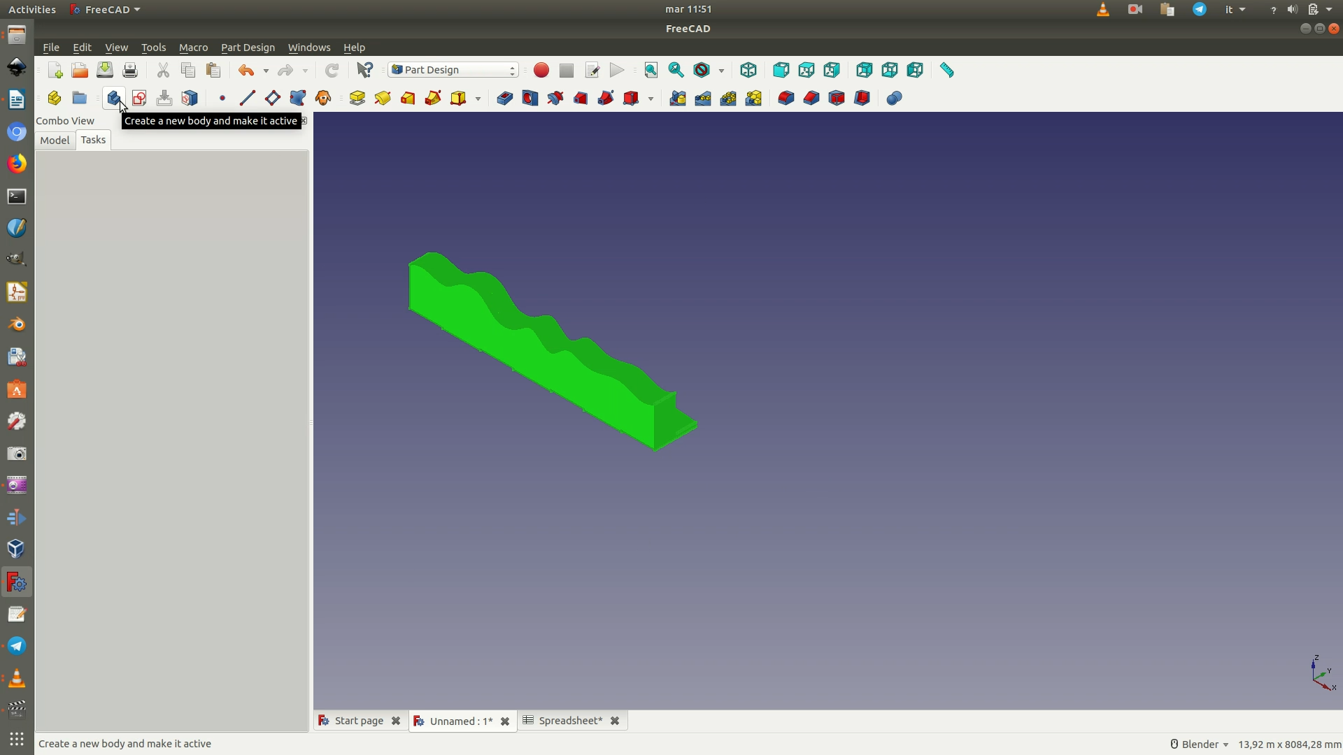
1. Switch to the Part Design Workbench. Select the Fusion element and click on the Create Body icon (or go through the menu Part Design > Create New Body). A pop-up warning sign will appear, and you can click OK. Again, the left sidebar will inform you of this change by adding a new Body element, this time below the previous Fusion element, without replacing it. Additionally, the curves will no longer be of the colors you had assigned them, but will be gray again.
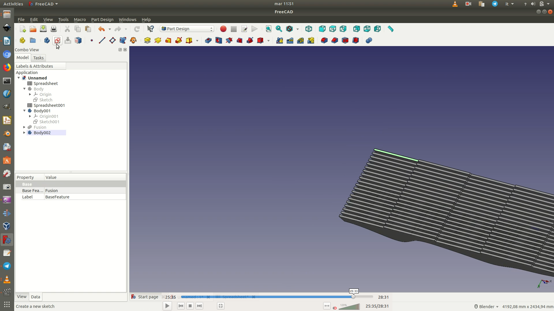
2. Rotate the object so that its base is facing you. Select any one of the faces of the base, as long as it is not one of the protruding ridges. Click on Create a New Sketch. This way, the sketch you are going to create now will already be laying on the base of the curves. You will now use a new command, External Geometry (Sketch > Sketcher geometries > External geometries), which will allow you to see in your current sketch the projection of a geometrical element that is not part of your current sketch. Once you have selected the command, use the cursor to select the segments on the outer edges of the base of the curves. Look at the image below: the segments you need to click on are the ones that have turned purple in the image. When all four segments have turned purple, click ESC to exit the command.
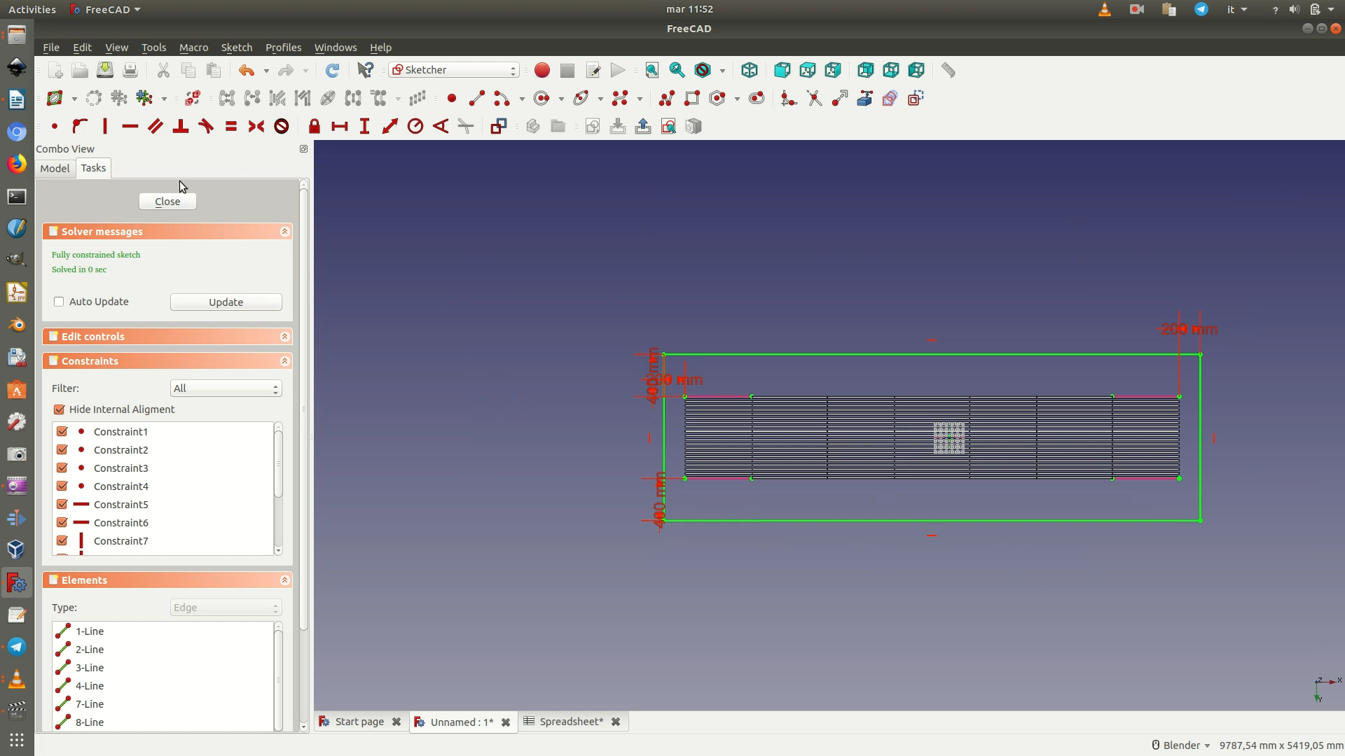
Now click on the Create Rectangle icon (or go through the menu Sketch > Sketcher geometries > Create Rectangle). Draw a rectangle around the base of the curves, making sure it is bigger than them. This is the green rectangle of the image below.
At this point, you need to define exactly the size of the base and position the curves in the center of it.
Select the top left corner of the rectangle and the leftmost point of the top left pink projection segment. Then apply a Horizontal Distance Constraint with length of 200mm (or the number that best fits your design).
Select the same two points and now apply a Vertical Distance Constraint with length of 400mm (or the number that best fits your design).
Now move on to select the bottom right corner of the rectangle and the rightmost point of the bottom right pink projection segment. On these two points apply the same constraints as before, a Horizontal Distance Constraint of 200mm and a Vertical Distance Constraint of 400mm. Now close the sketch.
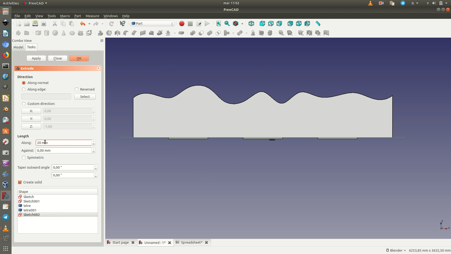
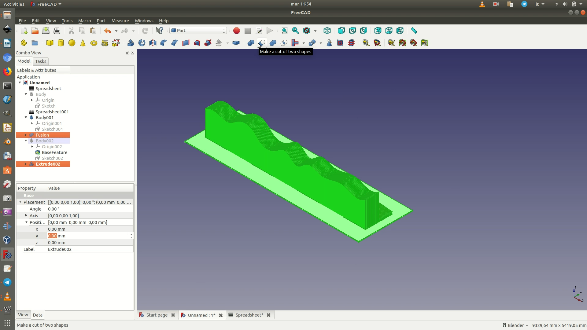
3. Move to the Part Workbench. Select this last Sketch and then Part > Extrude. On the panel that appears on the left, under Length, type in 20mm and then click OK. This because the base will be cut out of a 20mm-thick wood sheet. If you are using another material or sheets of another thickness, type in that amount.
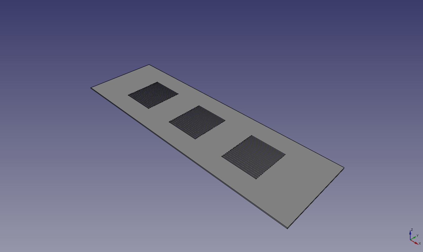
4. You now want to cut out, from the base, the slits where the ridges of the curves will fit into. From the left sidebar, select, in this order, the last Extrude element (the base) and the Fusion element (the curves). You use CMD+click (on a Mac) or CTRL+click (on Windows and Linux) to select multiple elements. Now click through Part > Boolean > Cut.
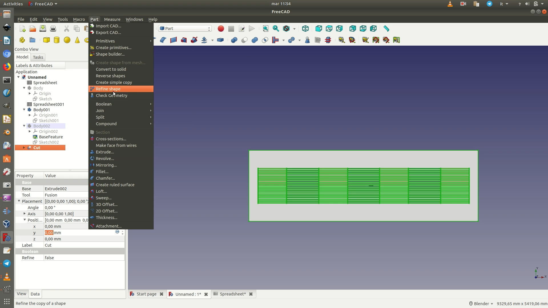
5. As a last step, you need to clean up the shape to remove unneeded subdivisions from the surface of the base. To do this, first select the last Body element in your left sidebar and hide it (hit the spacebar or right-click and select Hide Selection). Select the Cut element from the left sidebar. This element is essentially the base of the object with the slits cut out. Go through Part > Refine Shape.
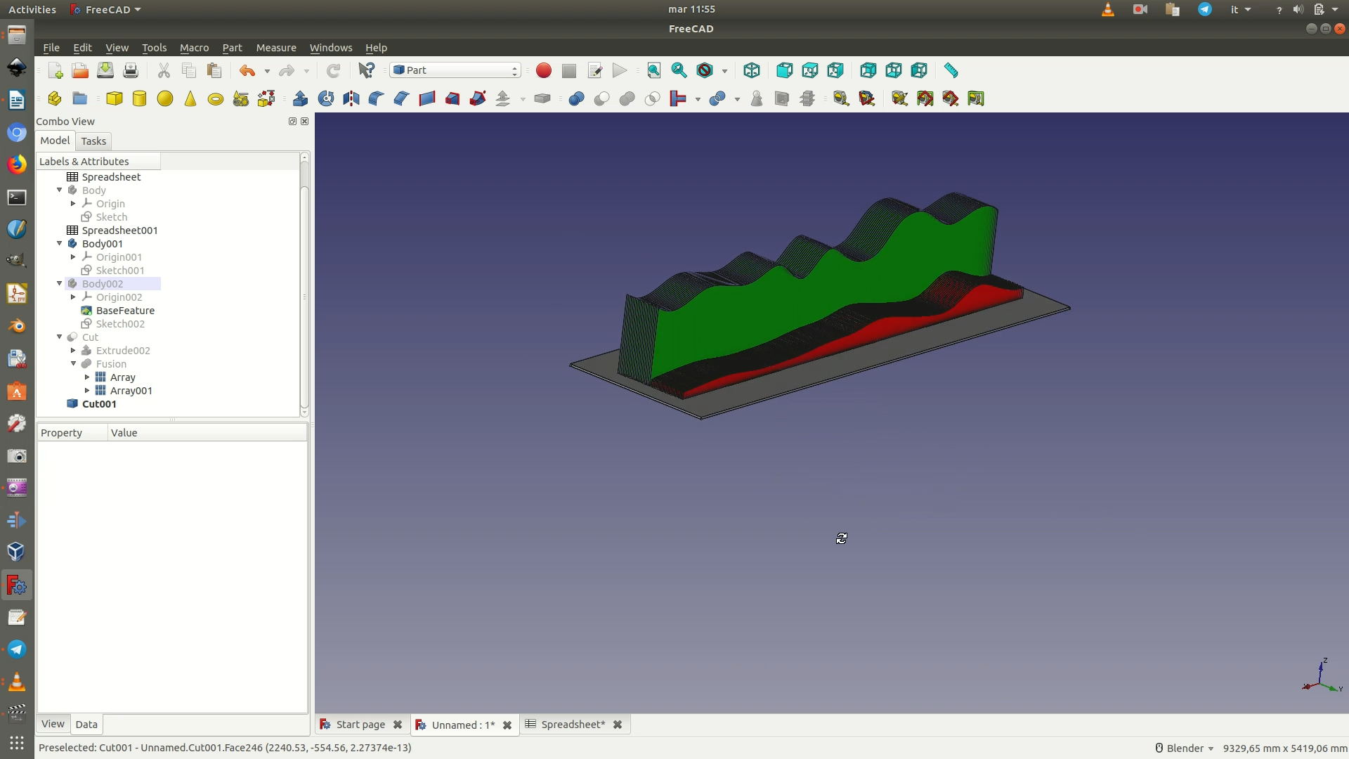
Now, to check that everything went well, explore the left sidebar and expand the one-before-last Cut element. You should see an Extrude element and a Fusion element. Expand the Fusion element, select both of the two Array elements nested within it and right-click to choose Show Selection.
You can now rotate the object around to double-check that everything went smoothly.