3D Modeling · 3D Data Map
Part 1 - The base map
Full Video Tutorial
Workflow explanations
Download final 3D modeling files
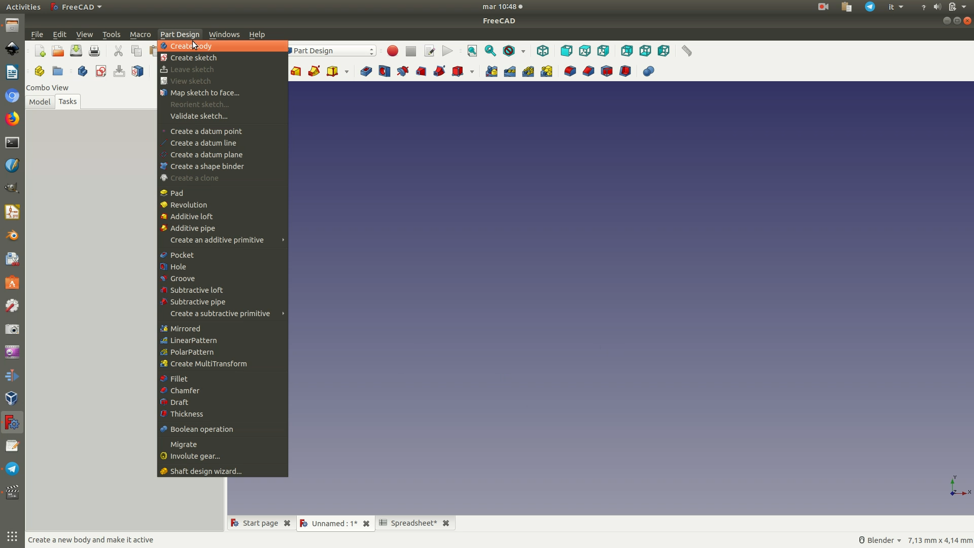
1. Opening FreeCAD and create a new project by clicking on File > New. Open the Part Design Workbench, as shown in the image, by clicking on the dropdown menu where you now see Start. This workbench contains all the commands used to model the single parts of the object.
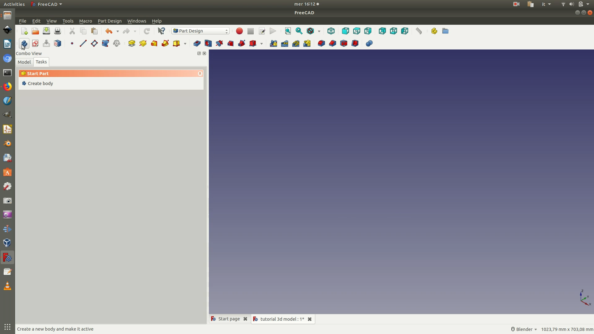
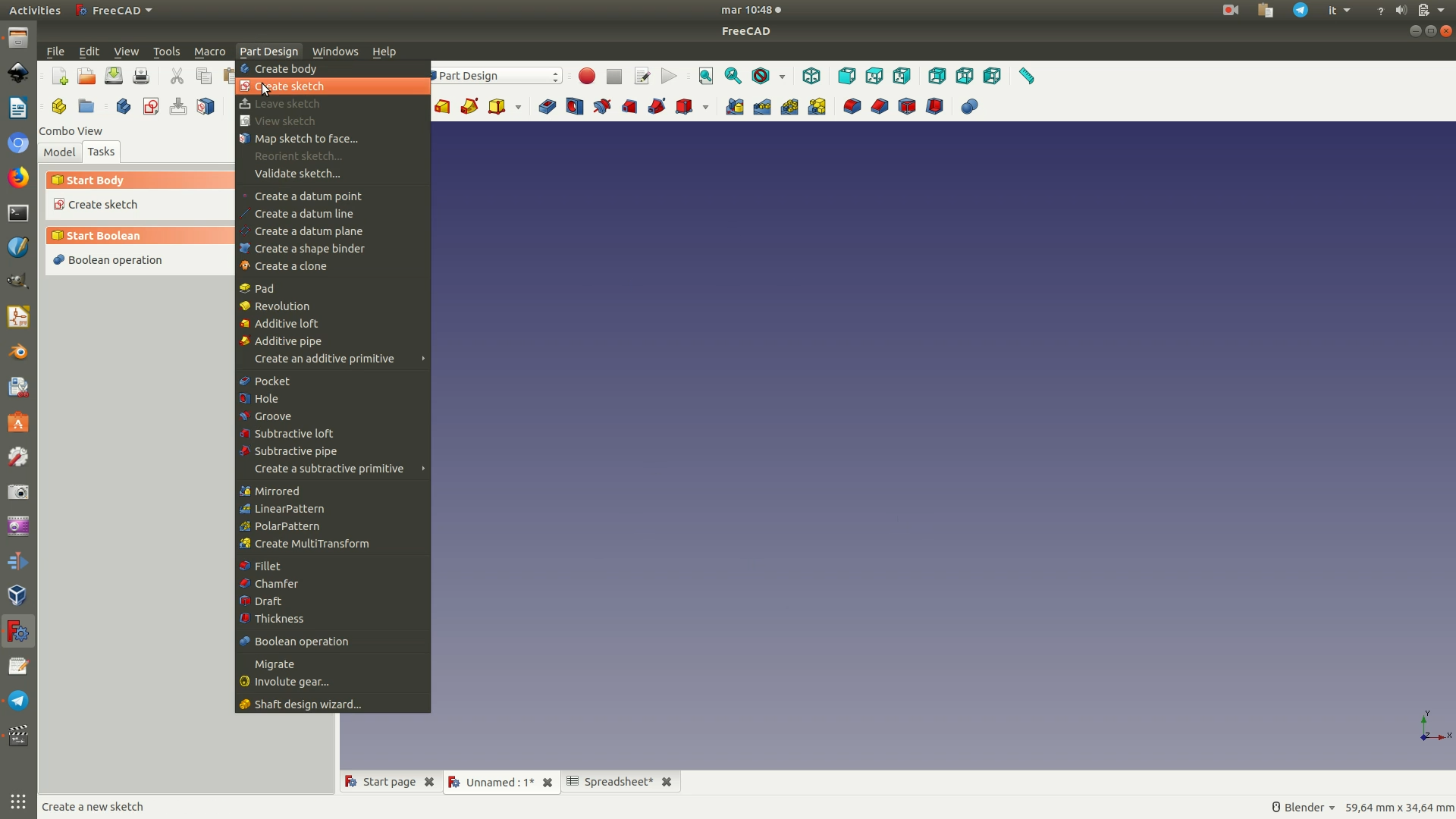
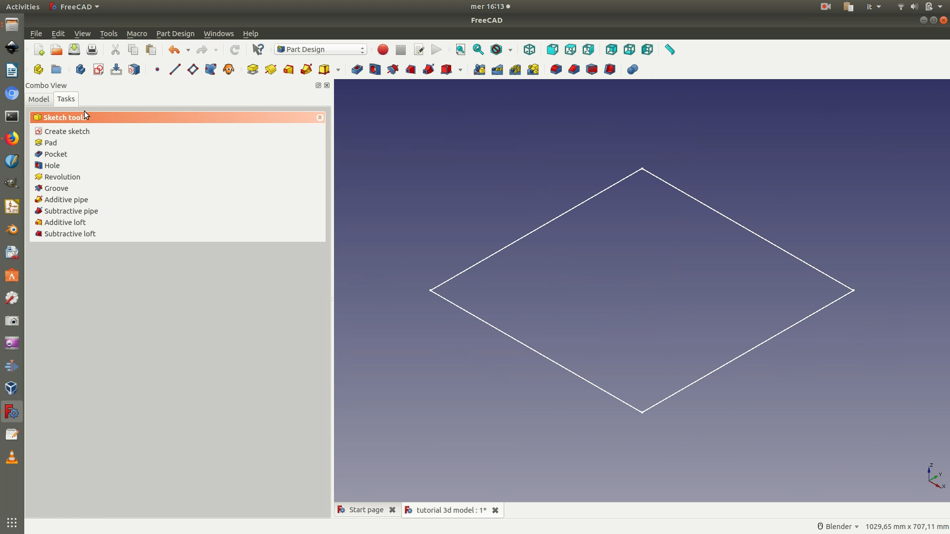
2. Create a new body (the container for your design) and a new sketch (the 2D drawing of your object). To do this, first click through the menu Part Design > Create Body, then through Part Design > Create Sketch.
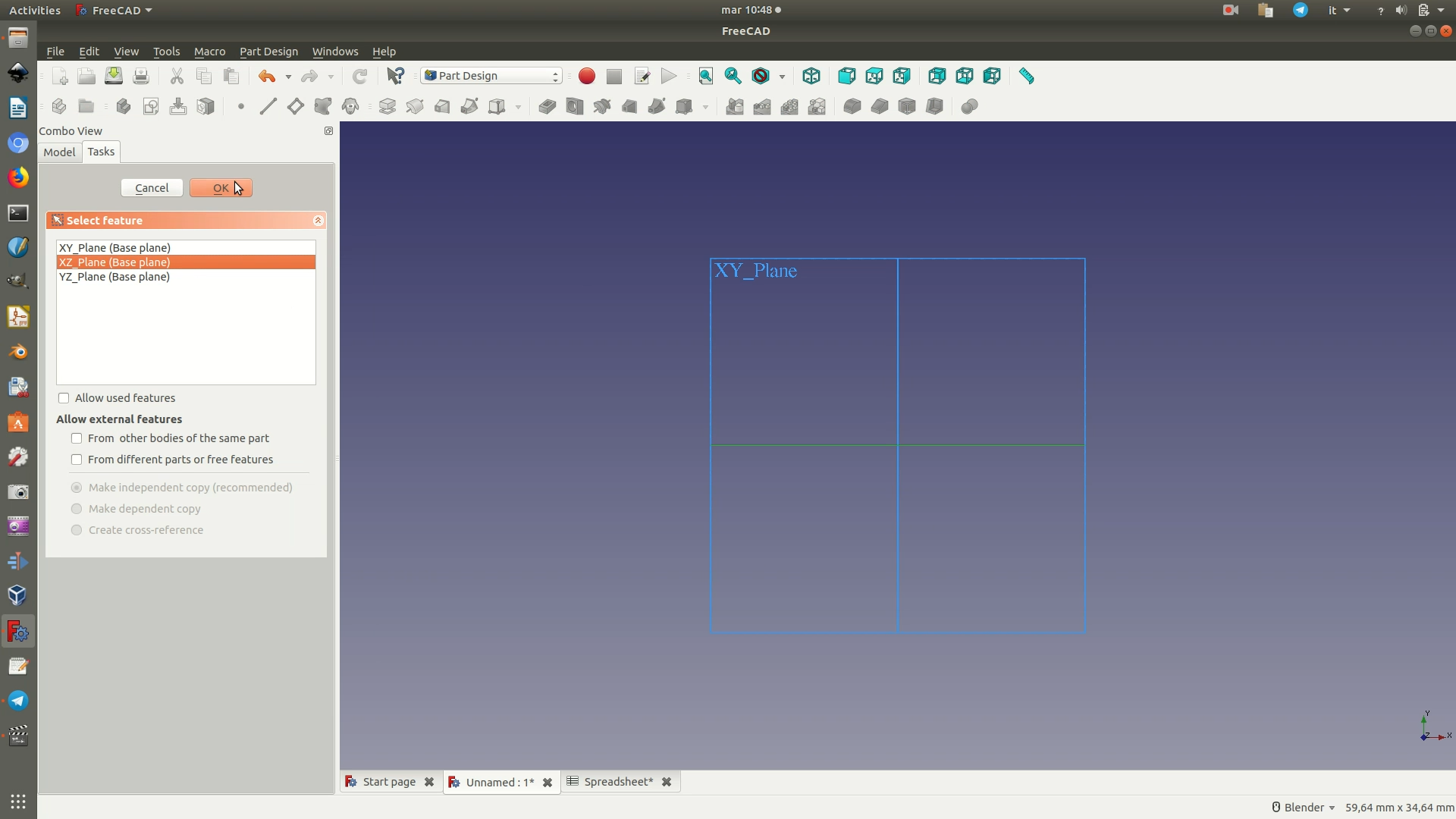
Once you've done this, select the XY Plane from the Combo View Panel that should have appeared on the left side of the screen and click OK.
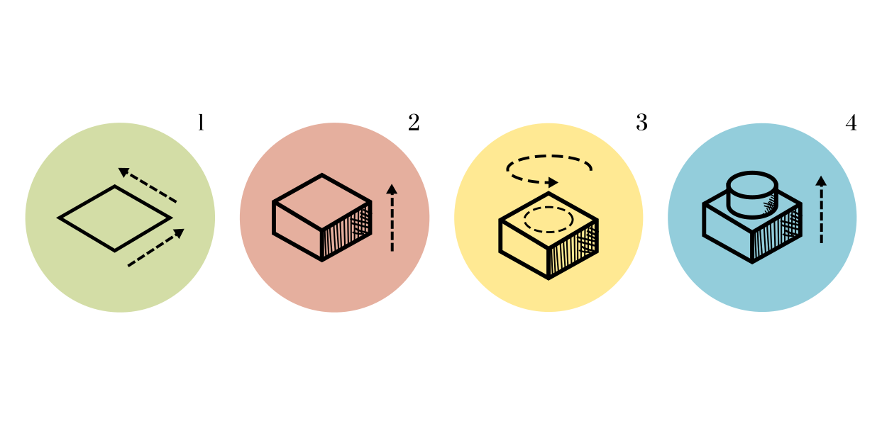
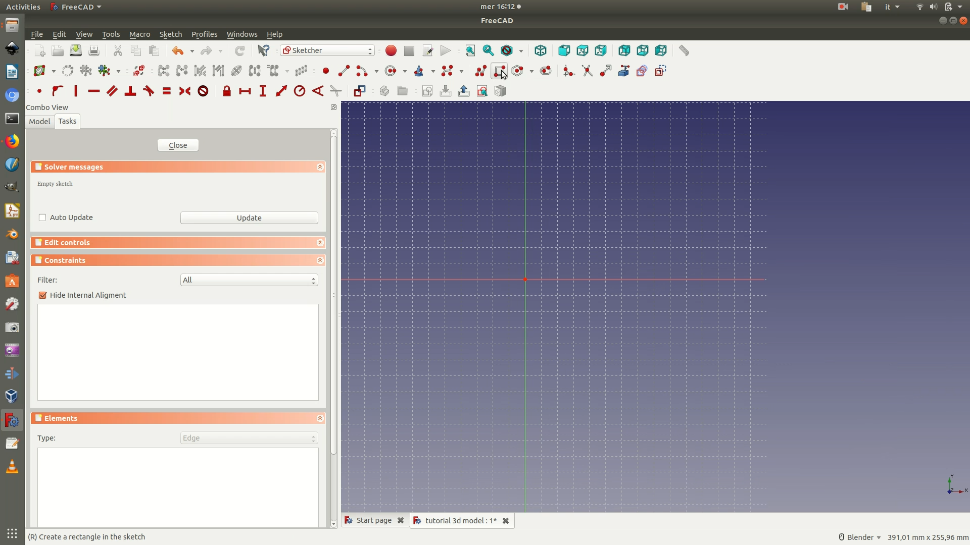
3. You should have been automatically redirected to the Sketch Workbench, if not select it manually from the workbench dropdown. Then, click through the menu Sketch > Sketcher Geometries > Create rectangle. You can now draw a rectangle similar to that in the image below. Don’t worry about dimensions, we'll fix them else further on.
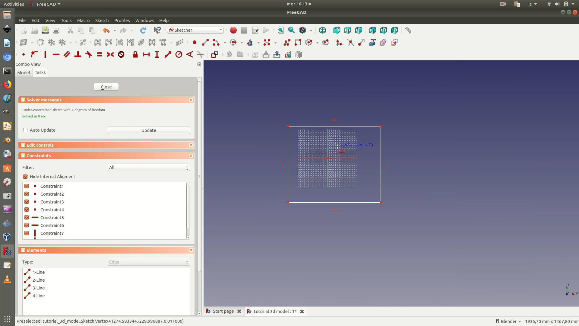
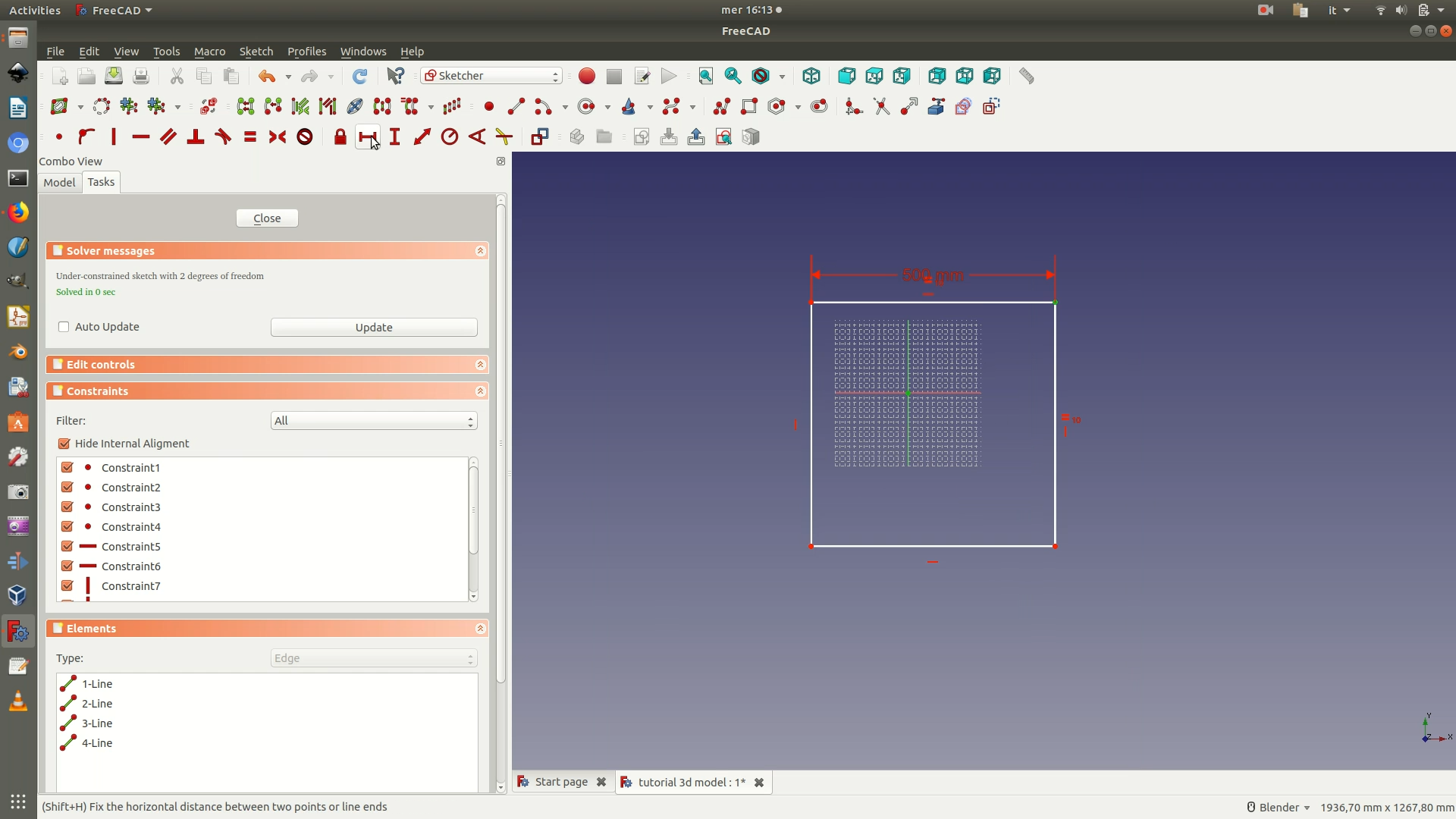
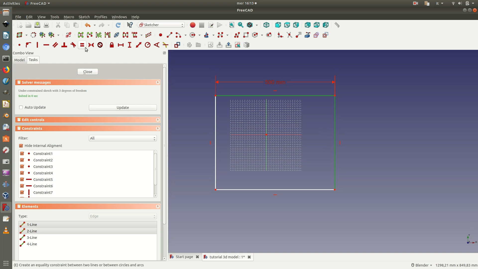
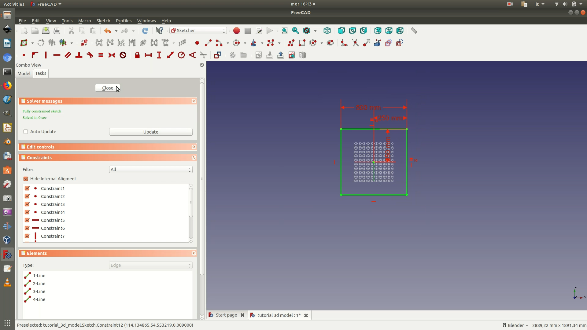
4. Select the top segment of the rectangle by clicking on it (selected elements turn green) and then apply the Horizontal Distance Constraint (Sketch > Sketcher constraints > Constrain horizontal distance). A pop-up window will prompt you to fill in the length value of the selected segment. Type in 500 mm. At this point, you want to apply the Equality Constraint between this top segment and one of the side segments. This constraint forces the sides of the rectangle to be the same length as the top and bottom, and will result in your shape becoming a 50x50 cm square. To apply this constraint, select the top segment of the rectangle and the right side segment and go through Sketch > Sketcher constraints > Constrain equal.
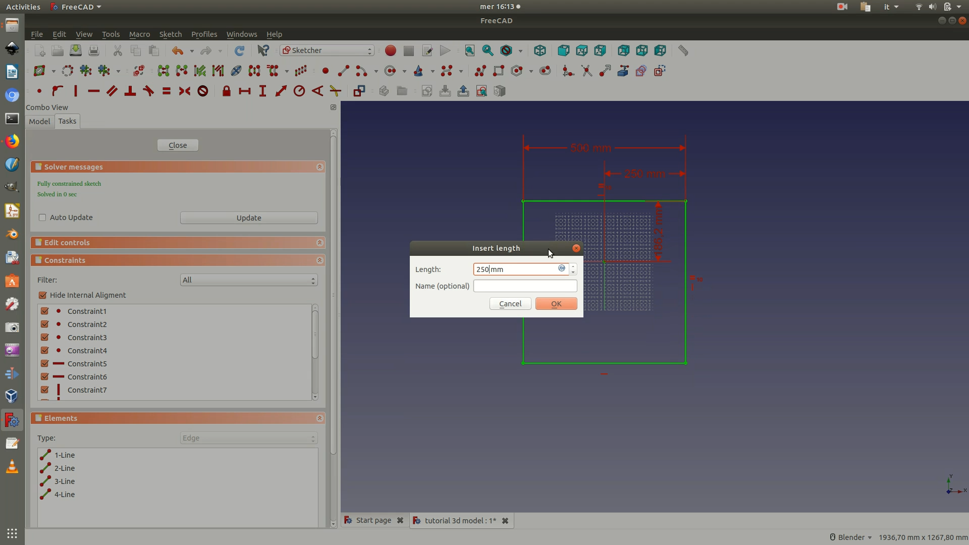
5. Position the square at the center of your plane. To do so, select the origin point and one of the corners of the square. Apply the Horizontal Distance Constraint and type in 250mm</code>. Select the origin and the corner of the square again, and now apply the Vertical Distance Constraint (Sketch > Sketcher constraints > Constrain vertical distance). Type in 250mm in the pop-up window that appears. Close the Sketch.
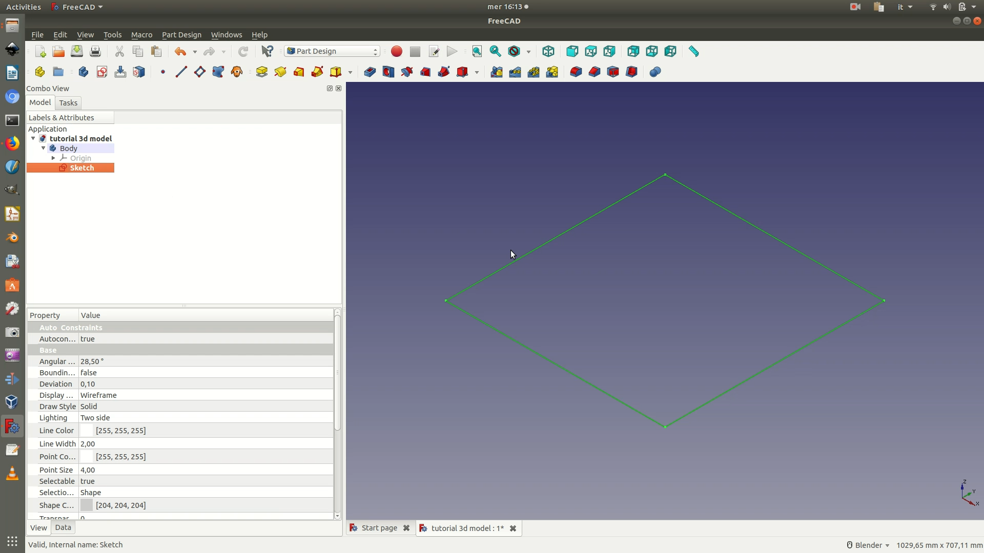
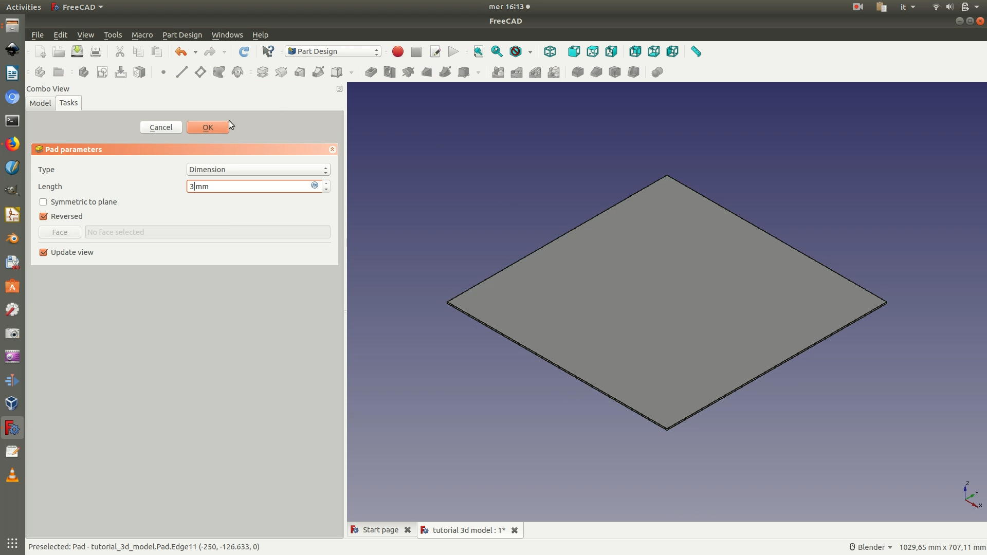
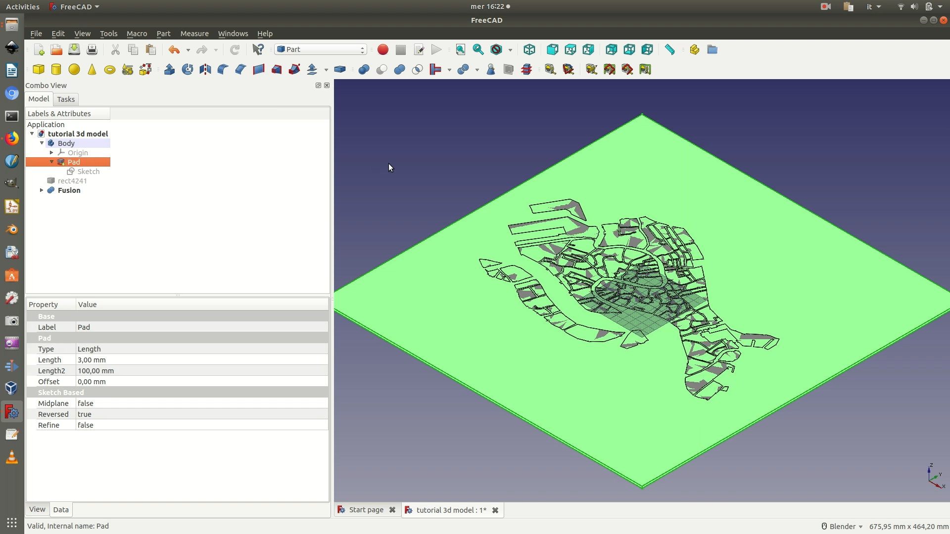
6. Select the sketch from the left side panel (see image below). Go through the menu Part Design > Pad. In the left panel you will be asked to type in a length parameter. Fill it in with 3mm (the height of your plexiglas sheet), and check the box with the option Reverse, this way the square will be padded towards the bottom of the XY plane. Click OK.
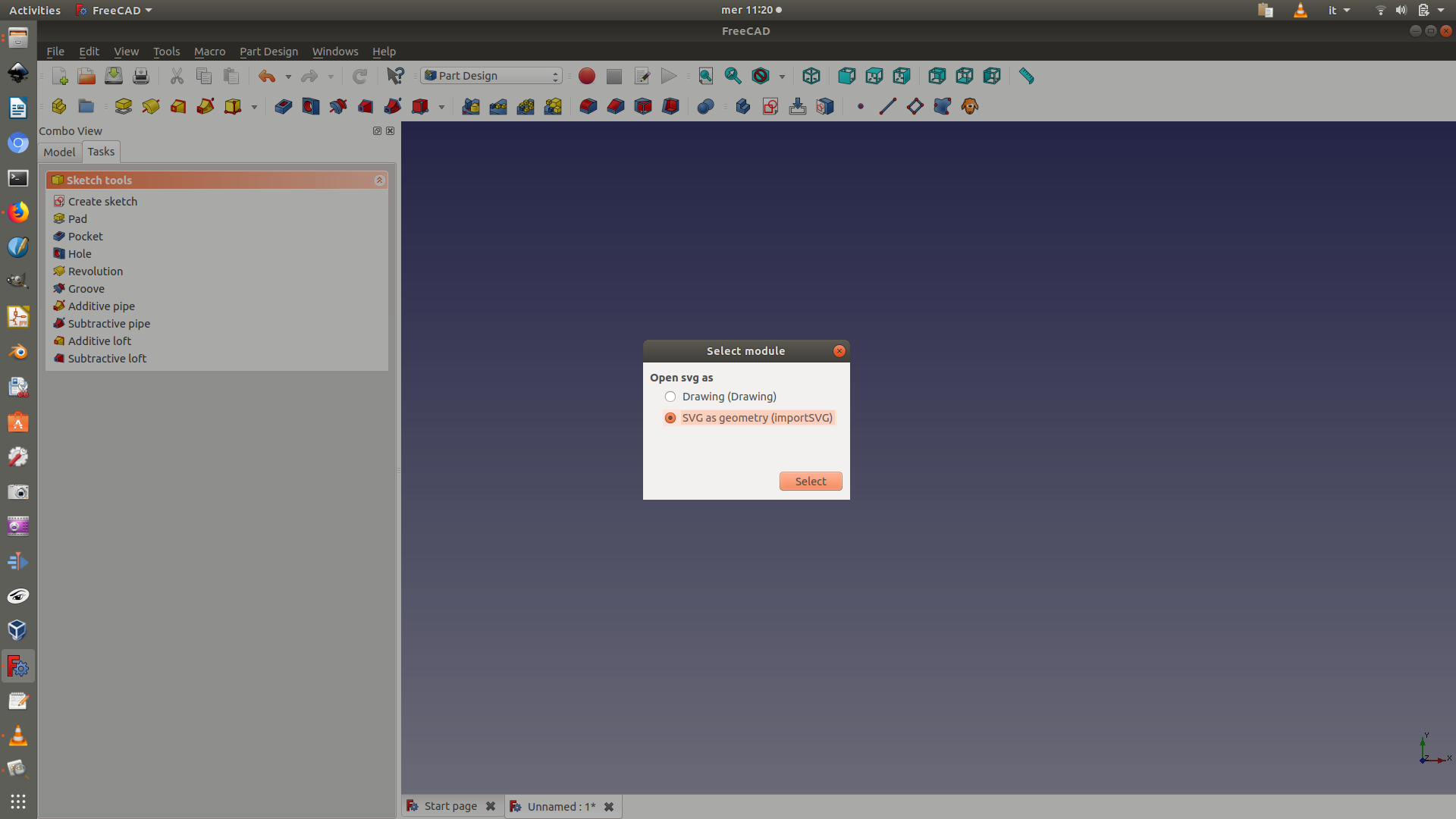
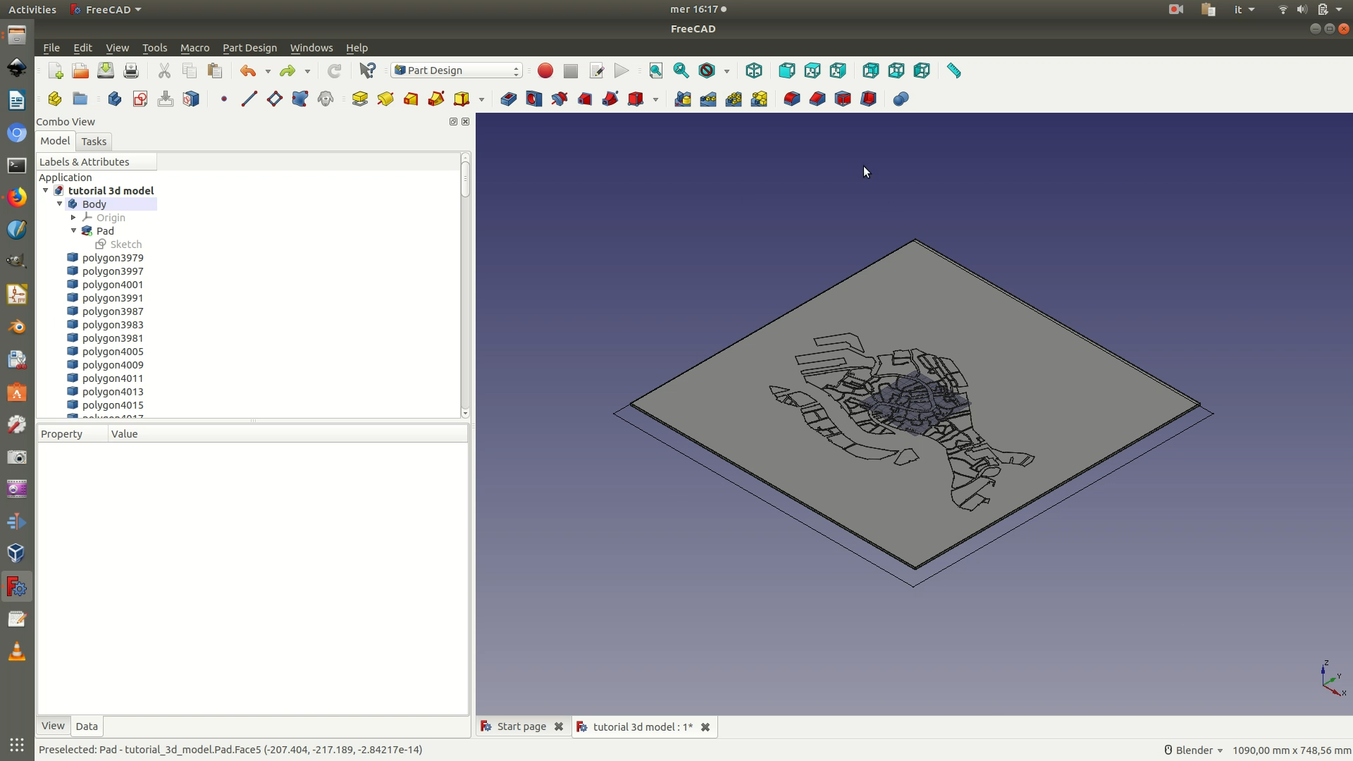
7. Import the .SVG file with the map you wish to engrave. To do so, click through File > Import > Select file. Make sure you click on the option to open SVG as geometry (importSVG) in the pop-up that appears. The map vectors should now be visualized on the XY plane.
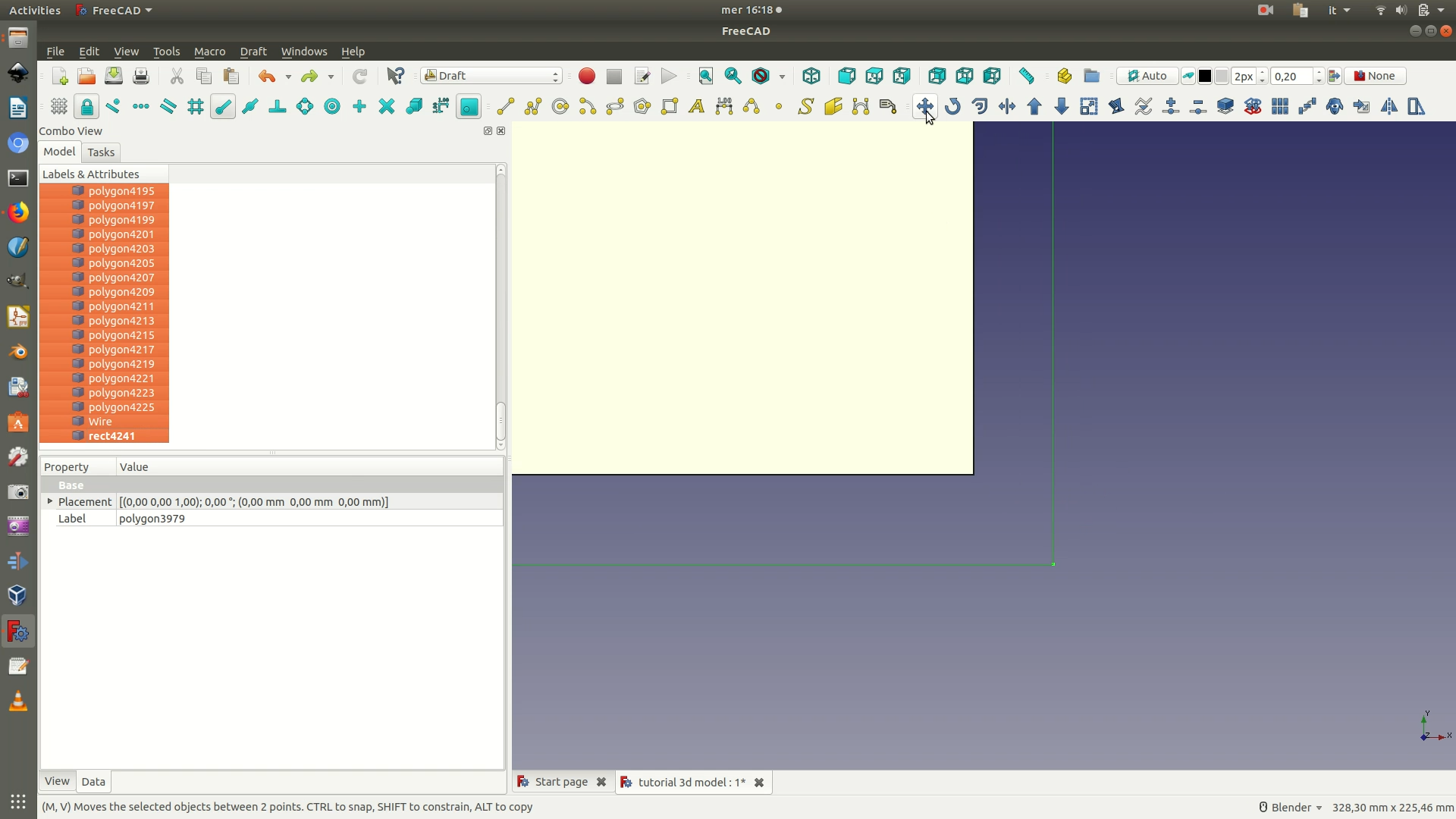
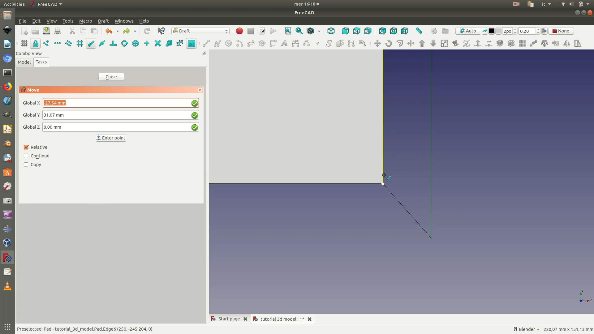
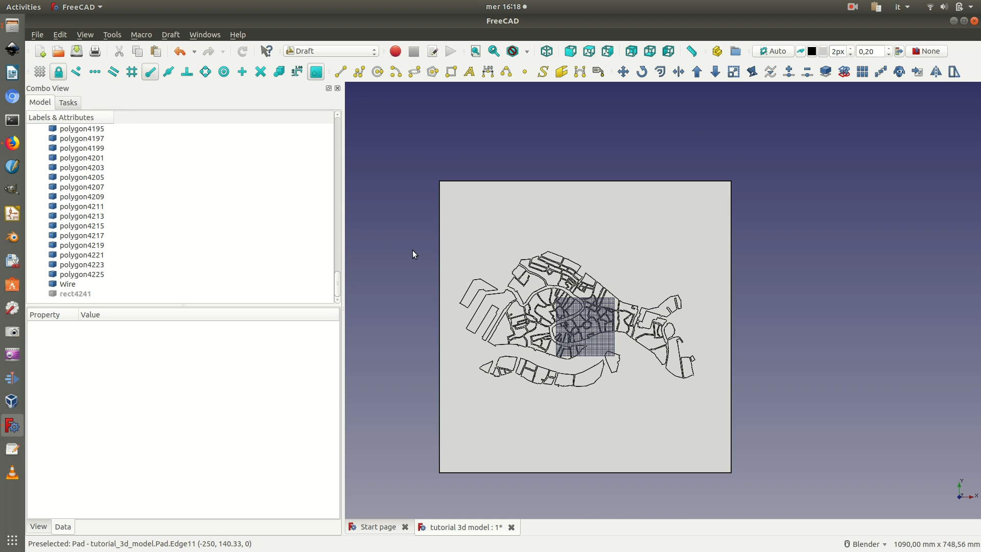
8. Move the imported vectors on top of the square base you have previously modeled. To do so, switch to the Draft Workbench and select the top view by going through View > Standard Views > Top. Select all the elements that are part of the imported .SVG by selecting all of them on the left sidebar pane (see image below). Move them by clicking through the menu Draft > Move. On the panel that has appeared on the left, make sure you deselect the Copy option. You will then define the movement of all the selected elements by choosing (clicking) the starting point and ending point of the movement.
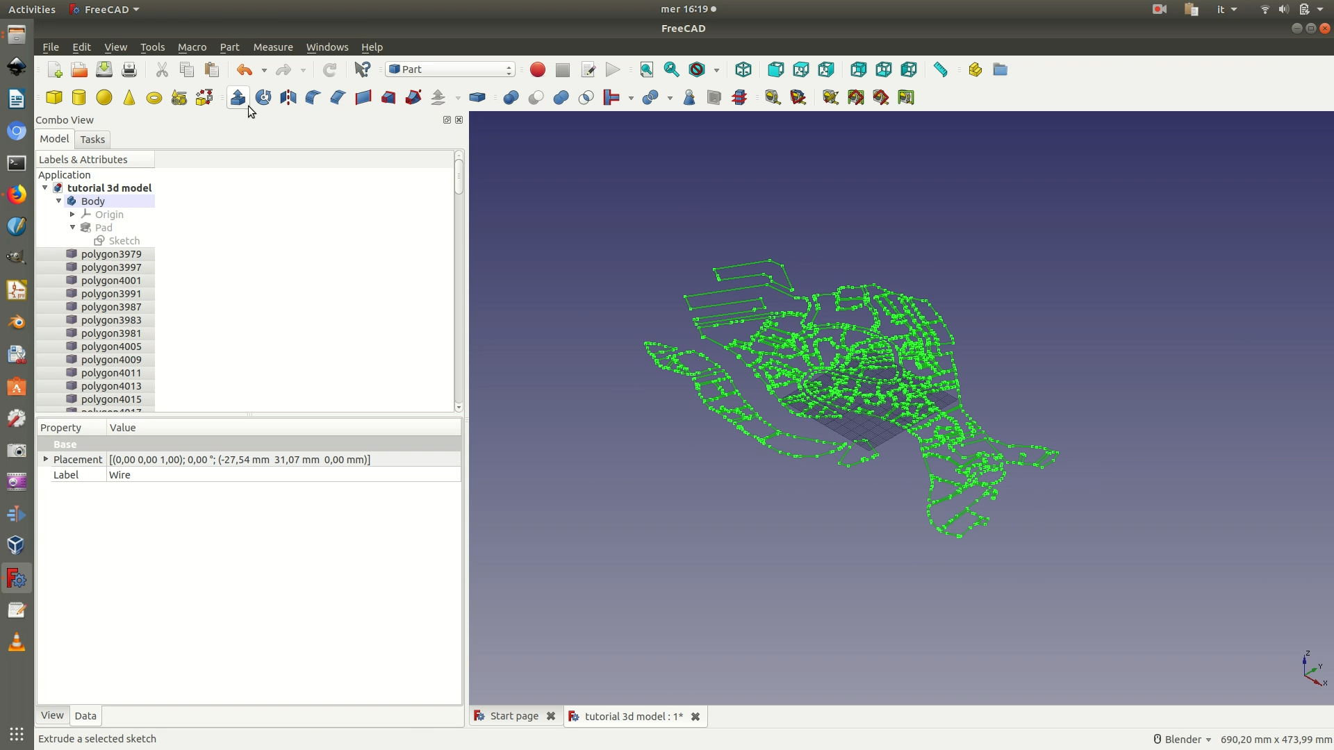
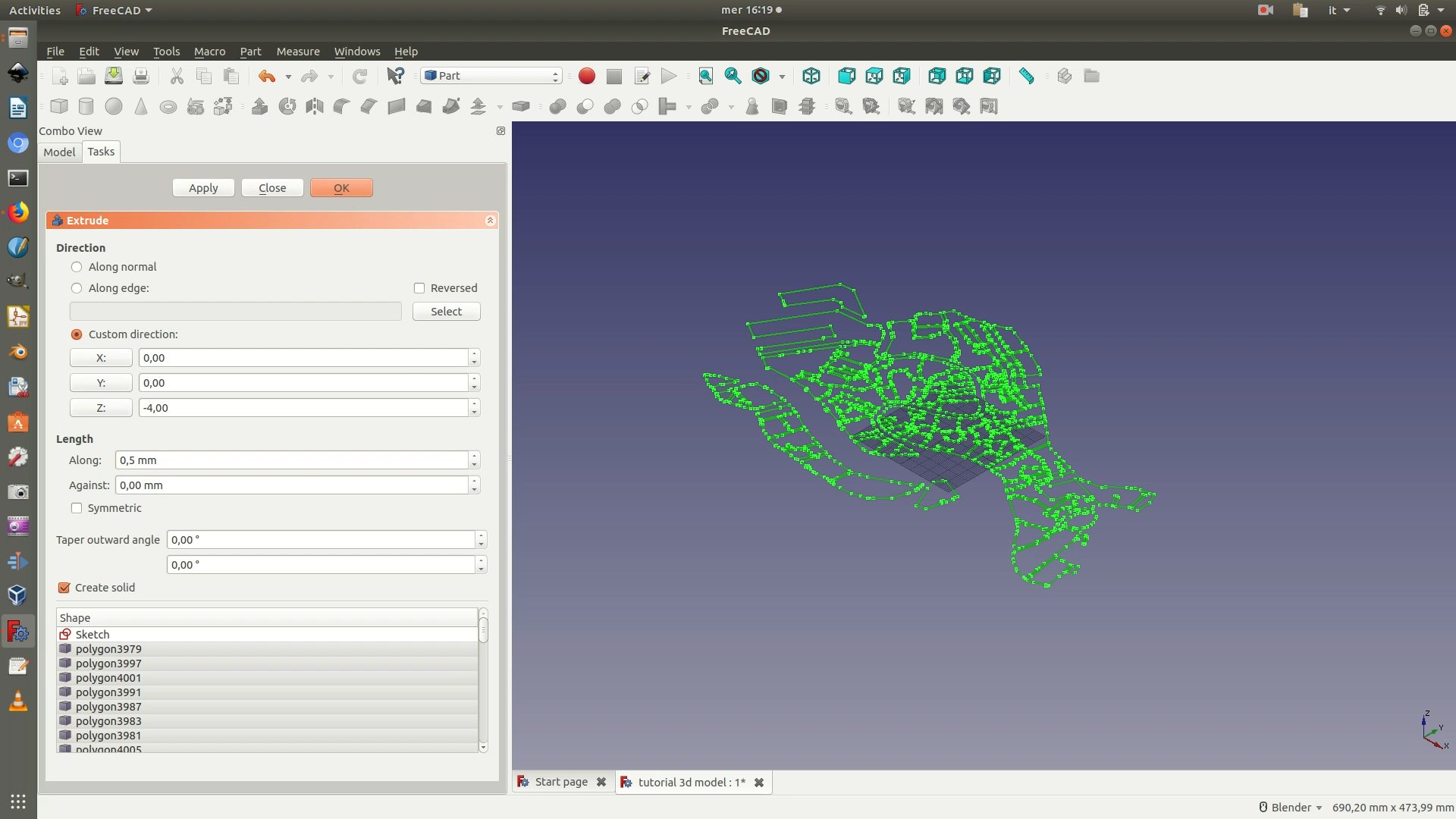
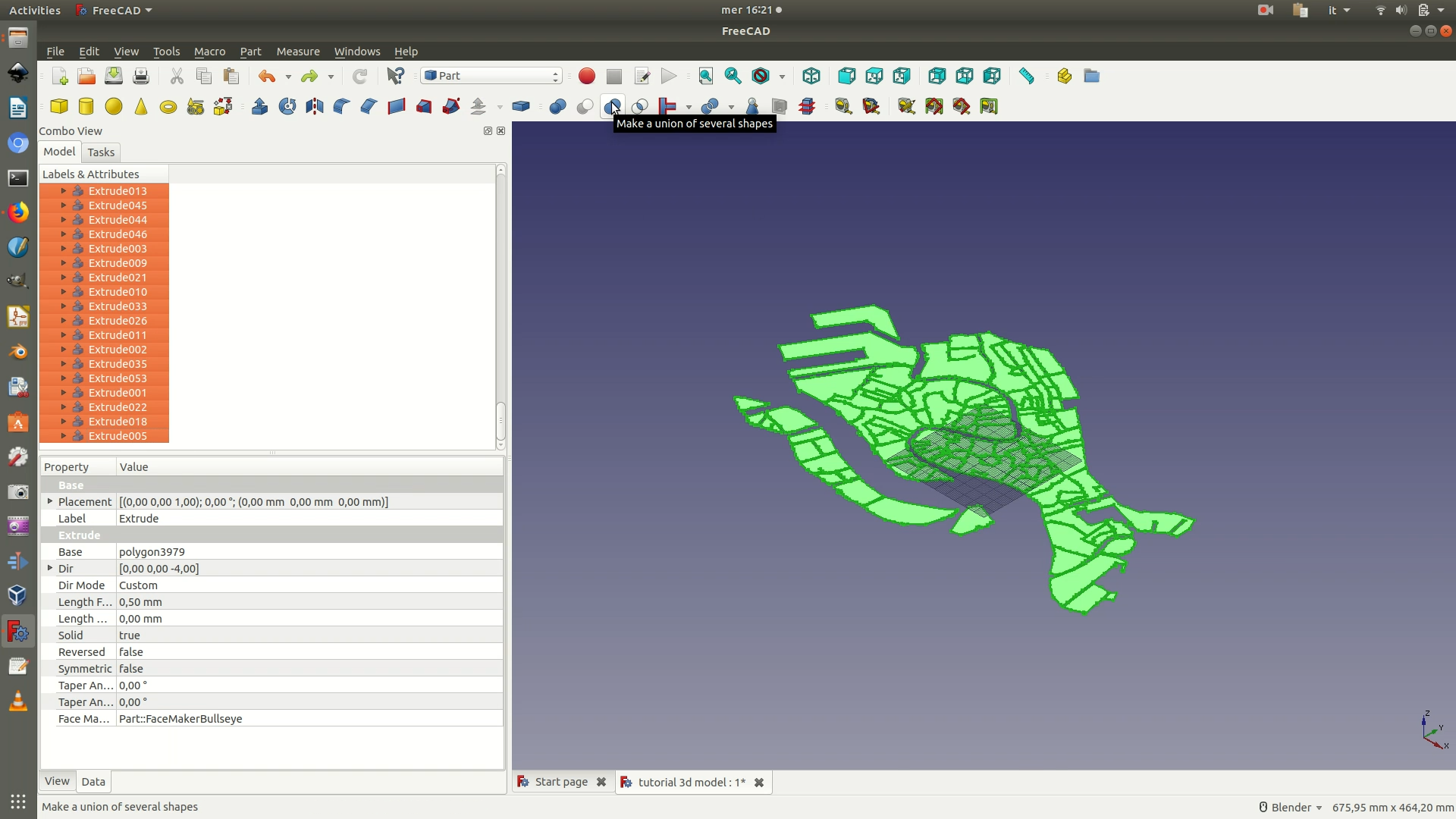
9. Once you are satisfied with the position of the vectors, switch to the Part Workbench and select the axonometric view by going through View > Standard Views > Axonometric. Hide the padded square element by selecting it from the left sidebar and right clicking Hide Selection (or hit the spacebar). From the left sidebar, select all the polygon elements and wire elements that are part of the imported vector map. Click on the menu Part > Extrude. In the selection panel that has appeared on the left, set the following parameters:
Custom direction > Z: -4Length > Along > 0.5 mm(this is how deep the map will be engraved on the plexiglas or the material you are engraving it upon).
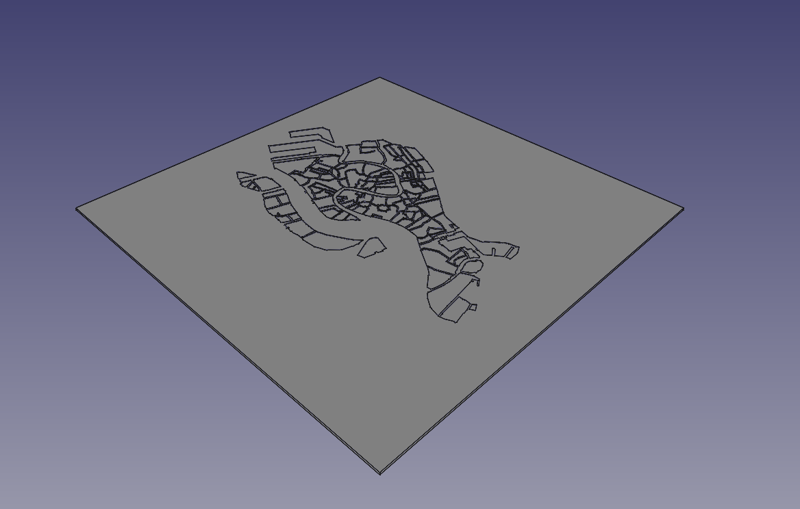
Click OK. Depending on your machines, it might take a few seconds, but at the end of the processing you will see a 3D model of the vectors and several new Extrude elements on the left sidebar.
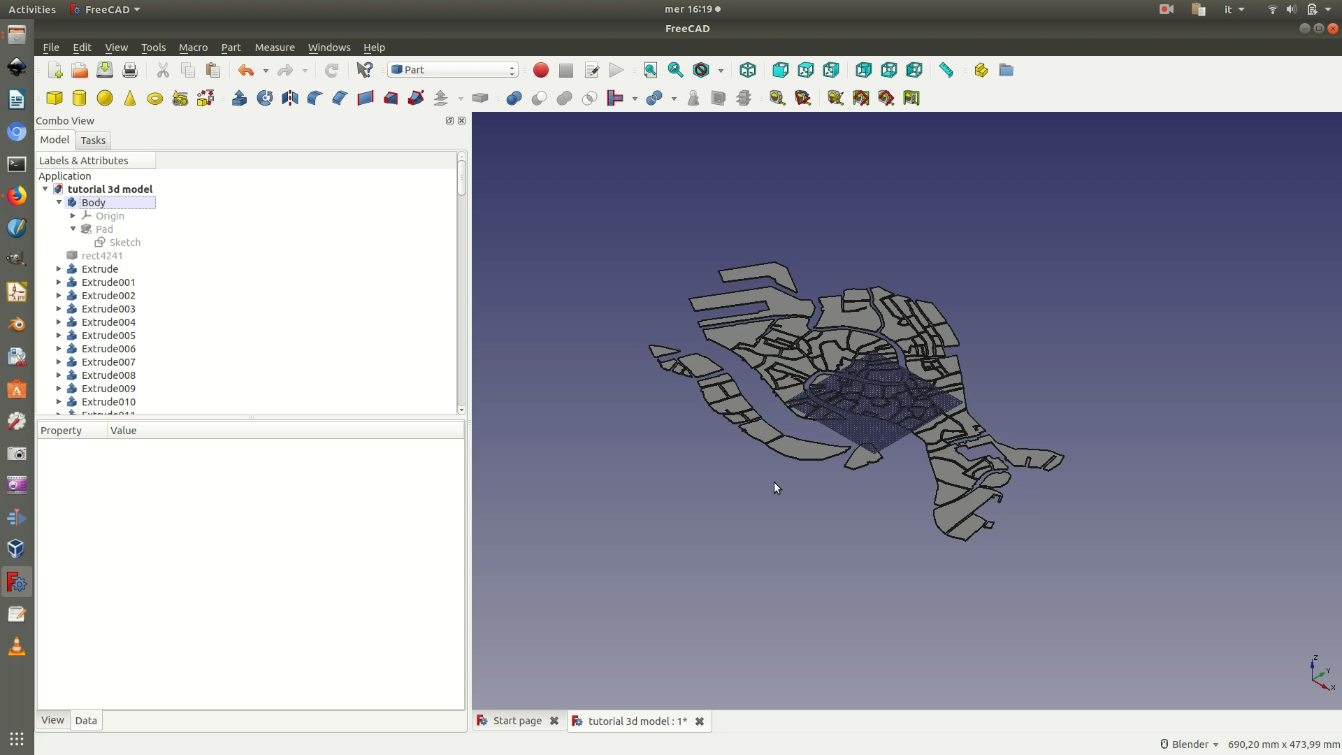
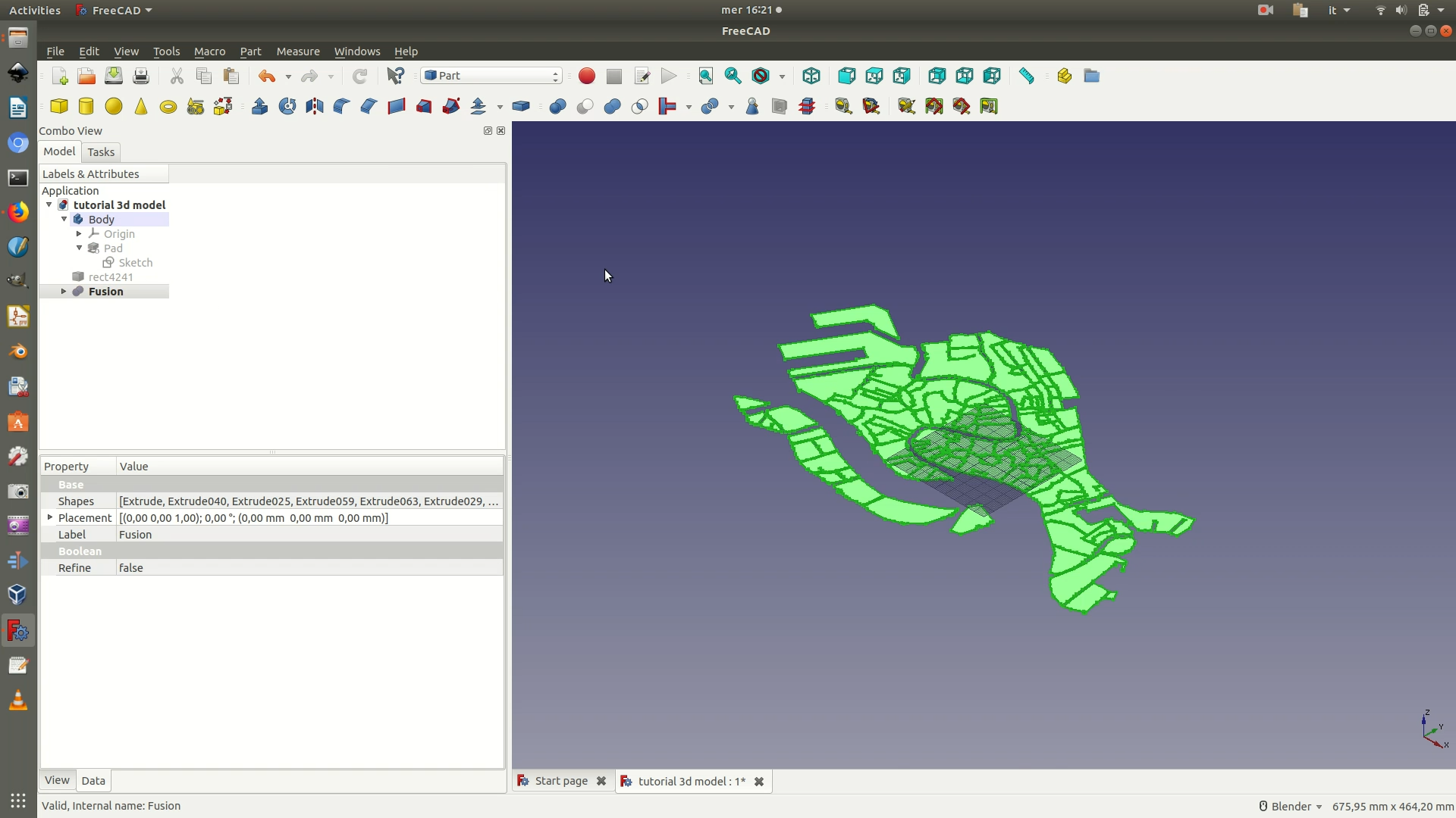
10. Unite all the extruded polygons that make up your map into a single element. To do so, select all the Extrude elements on the left sidebar and then go through the menu Part > Boolean > Union. This process might also take a bit of time to complete, depending on your CPU. When it’s done, you will see that, on the left sidebar, a Fusion element has replaced all the single Extrude elements.
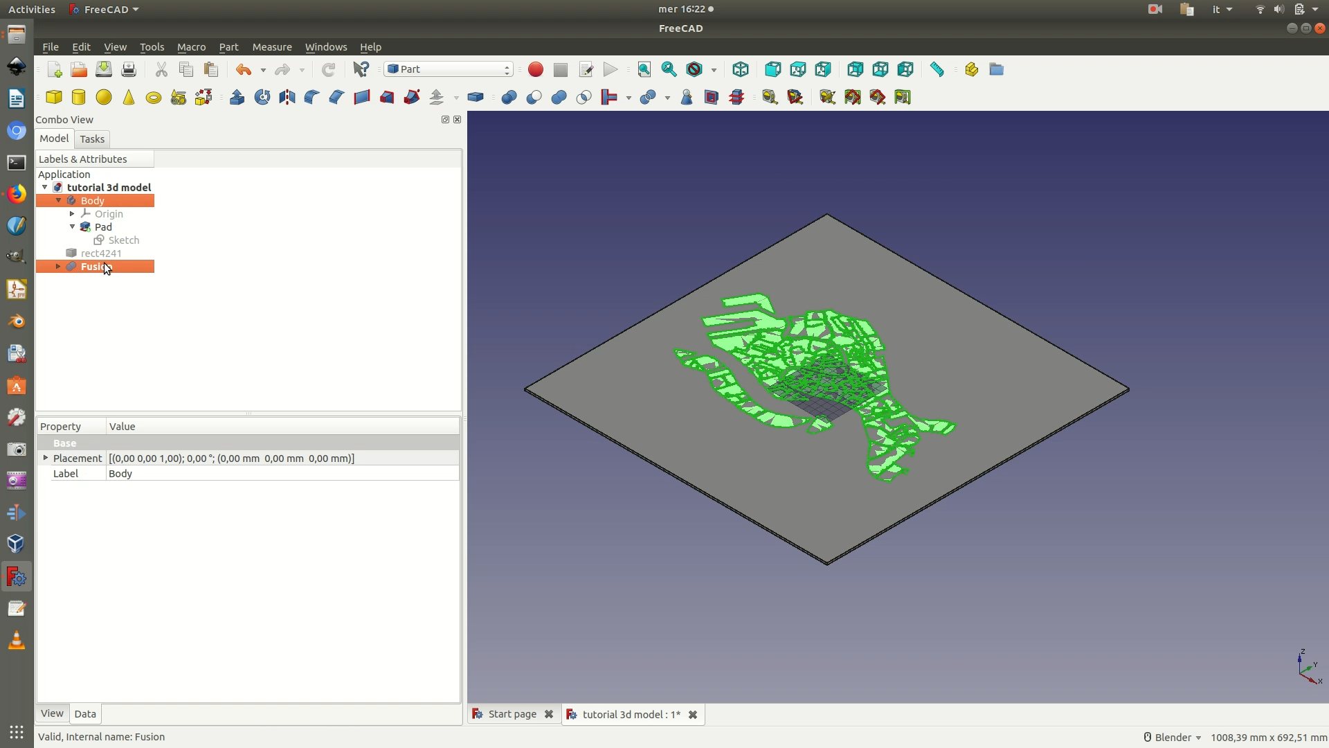
11. Unhide the padded square by selecting it on the left sidebar and right-clicking on Show selection. Now select both the Pad element and the Fusion element from the left sidebar, making sure that the Pad element is the first one you select. Go through Part > Boolean > Cut. Again, depending on your CPU and the complexity of the vector map, this process might take up even minutes. At the end of the operation, if you look at the left sidebar, you will notice that both the Pad element (the square) and the Fusion element (the map) have been grouped under a new Cut element.
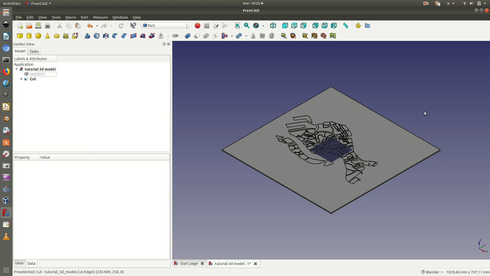
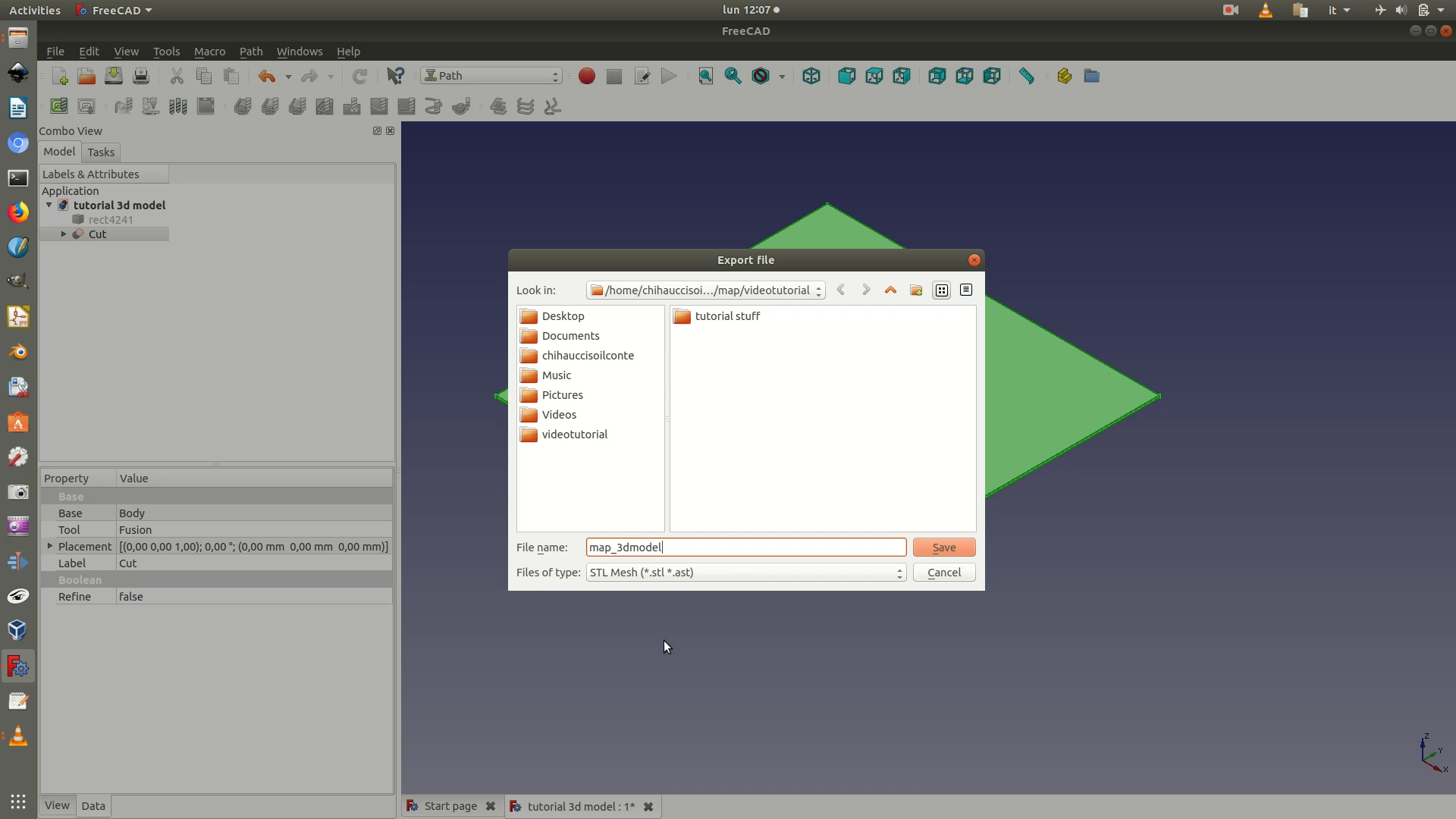
12. Select the Cut element, go through File > Export and save it as an STL Mesh (*.stl *ast). Then, also save the whole project as a FreeCAD file, with the .fctd extension.