3D Modeling and Electronics · Light Data Bars
Part 1 - Arduino Circuit and Program Code
Workflow explanations
Download schematics and Arduino code files
This tutorial contains step-by-step instructions on how to configure one data-driven light bar. To add more bars, switches and sensors to your Arduino, continue adding electronic components by repeating the steps 3-5 for the additional LEDs, sensors and switches. At the bottom of the tutorial you will also find schematics illustrating how to connect the different components when working with multiple bars. One Arduino will support up to 8 bars. If there are more than 8 bars in your design, you will need to get additional Arduinos. Additionally, keep in mind that one Arduino, when connected to the computer, has enough power to supply only 1 bar at the time. For this reason, as soon as you start working with the second bar, you will need to attach and plug an additional power supply.
Do not connect the Arduino to the computer while you are creating the circuit, but wait until you have all the electronics components in place, or you could damage your board and circuit.
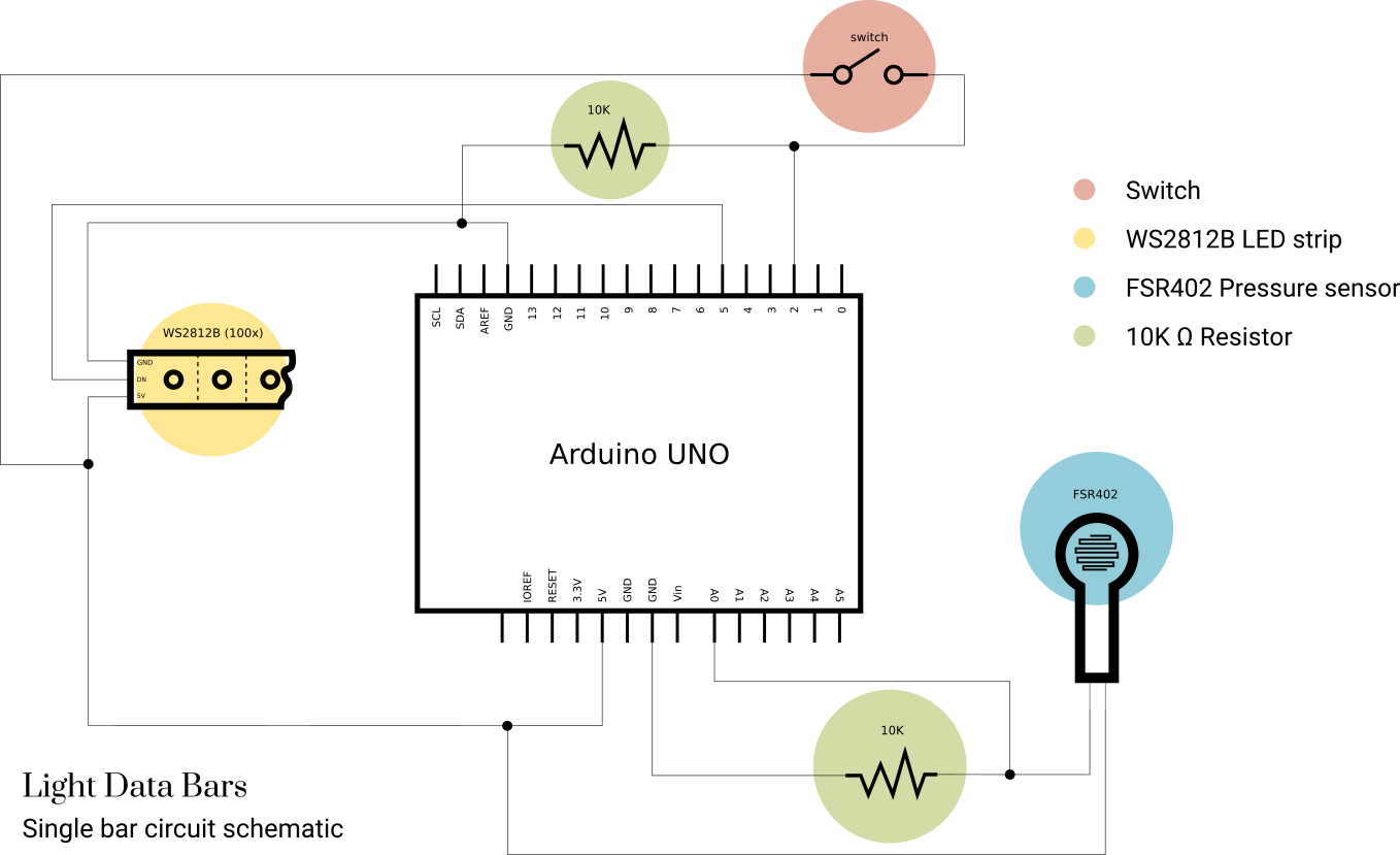
0. For reference, this is the basic schematics of the circuit for one light bar. At the bottom of the tutorial you will also find the schematics for a circuit with multiple bars.
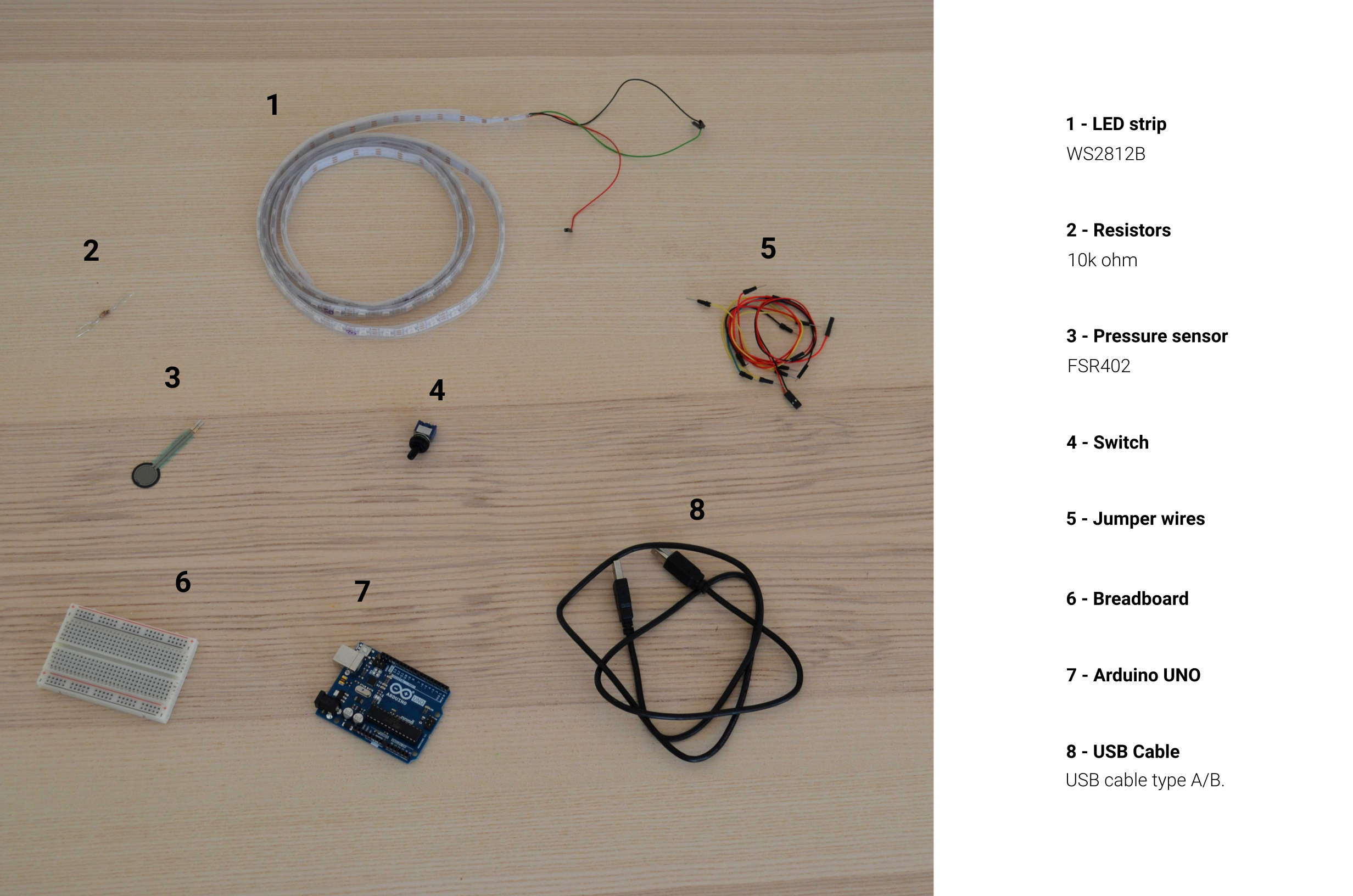
1. Find a clear flat surface and layout all the materials needed for the circuit:
- 1 Microcontroller Arduino Uno
- 1 Strip of 100 individually Addressable LEDs for each bar (model: WS2812B or similar)
- 1 Pressure sensor for each bar (model: FSR 402)
- 1 electronic switch for each bar
- 1 Breadboard
- A pack of Jumper wires
- 2 Resistors (resistance: 10K Ω)
2. Connect the breadboard and the Arduino.
A breadboard is a base that allows you to connect electronic components without the need to solder them together: you simply plug the components directly to the pins (holes) to create circuits. A standard breadboard has two horizontal strips, one at the top and one at the bottom, delimited by a red line and a black line. The pins within these strips are all horizontally connected. All the other pins at the center, on the other hand, are connected vertically.
An Arduino microcontroller is a physical programmable circuit board. You code its functioning through the open-source Arduino IDE installed on your computer, which you then also use to upload the code to the physical microcontroller.
Do not connect the Arduino to the computer while you are creating the circuit, but wait until you have all the electronics components in place, or you could damage your board and circuit.
A jumper wire is an electrical wire with connector/pins at its ends and is used to connect components together without soldering. To make the connection, you insert the jumper wire's pins into the pins of the electrical components you have to connect. Each wire can have a combination of male/female connectors at its two ends and you should choose the wire according to the pins of the components you are attaching: a male connector attaches to a female connector and vice-versa. All the pins of the breadboard are female, as are all the pins of the Arduino we are working with, so they require jumper wires with male connectors. Despite the different colors, all the wires are the same. It is however advised that you match the colors used in the image below, as they follow an established convention: red wires for positive charge (+), black wires for ground charge (-).
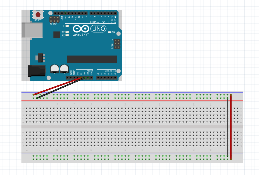
The first step is to provide power to the circuit. To do so, attach the jumper wires as shown in the image below. In this case, both the breadboard and the Arduino pins you need to connect have a female connector, so you need to use jumper wires with male connectors. Specifically, you should first use the red wire to connect the 5V pin on the Arduino board to a pin in the top line of the breadboard. Then, use the black wire to connect the GND pin (Ground) to a pin in the line below the previous. Afterwards, use another red wire to connect a positive pin in the strip at the top of the board with a positive pin in the strip at the bottom of the board. Finally, use a black wire to connect a ground pin in the strip at the top of the board with a ground pin in the strip at the bottom of the board.
3. Connect the LED strip to both the Arduino and the breadboard.
The LED strip you are working with is made up of individually-addressable LEDs, which means you can control the on/off status, color, blinking behaviour, etc. for each of them independently.
(Note: depending on your materials and design, you might have to first cut the LED strip into the desired length.)
The LED strip has 3 jumper wires already attached at its two extremes. Each of these wires corresponds to one of the three pins: one for ground charge (GND), one for positive charge (5V), and one for the data input controlling the LED's appearance and behaviour (generally labeled as Din, which stands for Data Input).
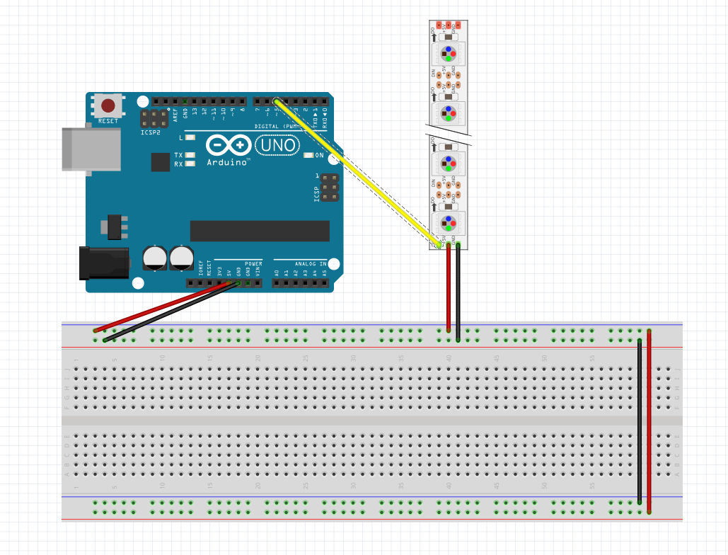
To make the connections, attach the wires as shown in the image below. The actual position of the pins on the LED strip might vary depending on the model, but you should match the connections between the pins:
- Red wire to connect the
5Vpin of the LED strip to a pin in the top line of the breadboard - Black wire to connect the
GNDpin of the LED strip to a pin in the second line of the breadboard - Yellow* wire to connect the
Dinpin of the LED strip to the~ 5('digital 5') pin on the Arduino board.
*You can use any color you wish, preferably other than red or black, for readability.
4. Connect the pressure sensor to both the Arduino and the breadboard.
The pressure sensor or force sensor is essentially made up of tiny circuits that bend when subject to pressure. The bend is imperceptible to humans, but it creates a difference of potential between the power poles of the sensor. Such difference can be quantified, depending on the amount of force applied, and used as data - in this case as input data for the LED strip. The pressure sensor has two pins at its end for the power supply. Unlike the other cases encountered, there is no specific pin assigned for the (+) and (-) charge, and they can be used interchangeably.
To connect the pressure sensor, you first need a jumper wire with one female and one male connector. The female connector attaches to the sensor, the male connector to the breadboard. Use a red jumper wire to connect one pin of sensor to a pin in the bottom line of the breadboard. Then, use a black wire and attach the female connector to the sensor. At this point, things change slightly in comparison to what you've done before. This black wire sends a charge that has been modified by the pressure applied to the sensor. You need to send this information to the Arduino, so that it can calculate and quantify the pressure applied to the sensor to use it in its program. To do so, the black wire can't be connected directly to the ground strip of the breadboard, but it needs an intermediate step: connect it to one of the pins in central area of the breadboard. Then take a green wire and insert it in a pin which sits on the same vertical line as the previously inserted connector. Attach the other end of this green wire to the A0 ('analog 0') pin of the Arduino board. As a final step, close the circuit by using a 10K resistor and a black wire, as shown in the image below.

5. Connect the switch to both the Arduino and the breadboard.
The switch is used as an analog input to give commands to the Arduino. In practice, the switch connects or disconnects the electrical flow. In this case, we are using it to tell the Arduino whether it should light up the LEDs according to the actual JSON data stored in its memory or according to the data from the pressure sensor.
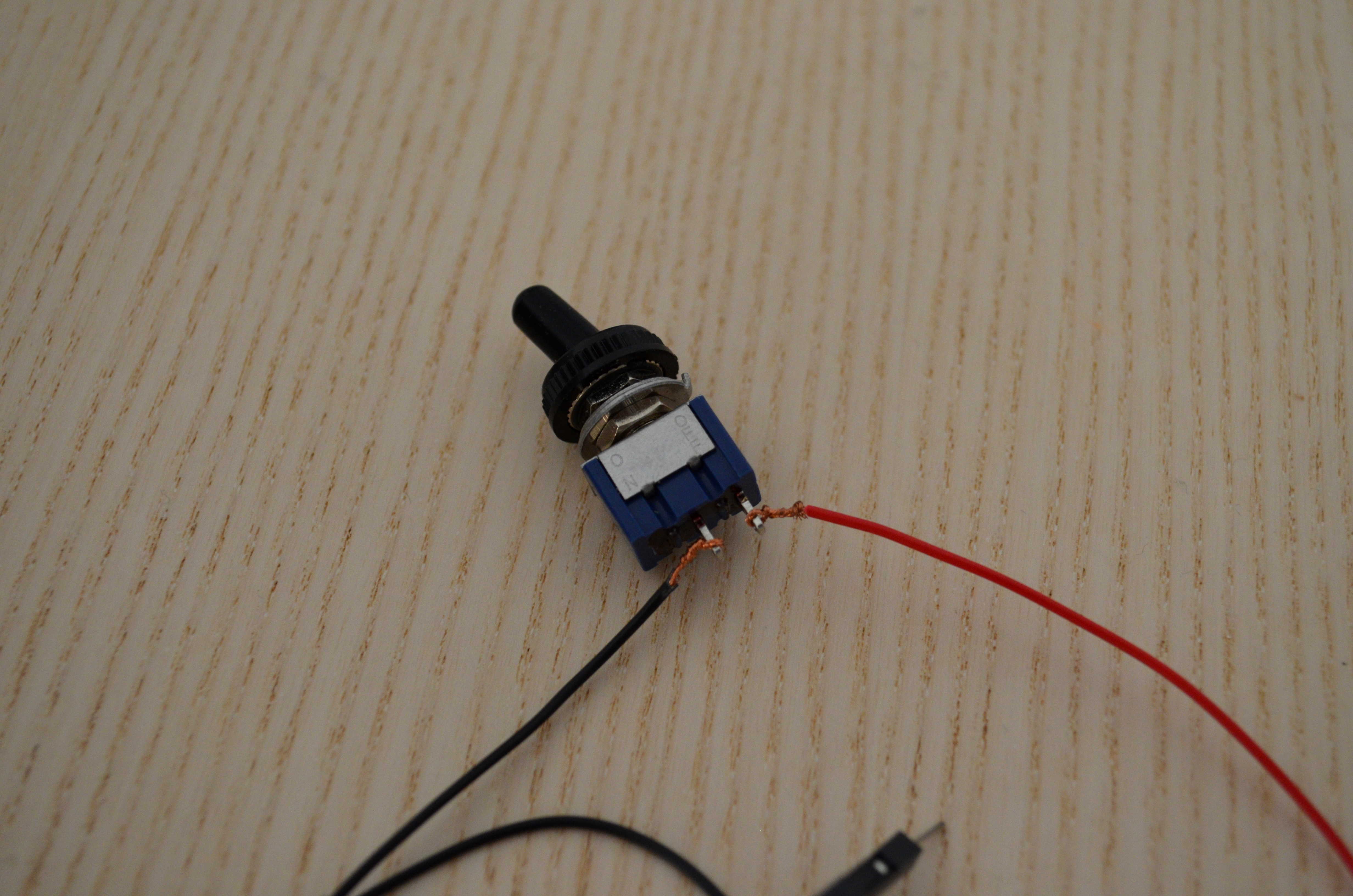
Because switches are used in many different contexts, it could be that your switch is not specifically designed for a breadboard and so doesn't have the usual male/female connectors you've seen on the other components so far. This is not a problem, as you can peel the jump wires with a wire stripper or with scissors and then twist the copper around the connectors of the switch, as the first image below shows. If you know how to solder, you could also solder them in place.
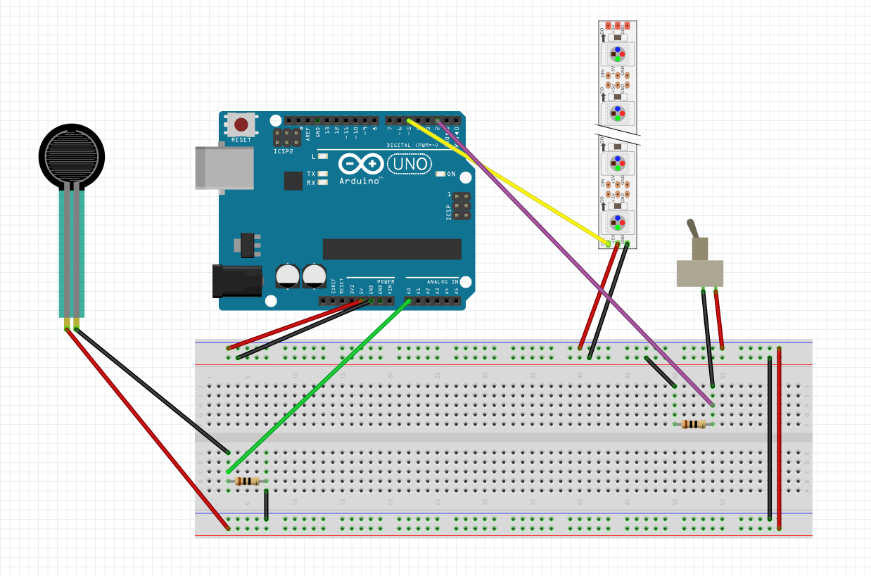
Connect the wires of the switch to the end to the Arduino as shown in the second image below. In short, you are replicating the reasoning behind the way you connected the pressure sensor in the step before:
- Use a red wire for the input charge (+)
- Use a black wire and a purple wire to send the electrical signal (or absence of it) to the Arduino, linking the purple wire to the
2('digital 2') pin of the Arduino board - Use a resistor and a black wire to close the circuit
The circuit is now ready and you can go to your computer to begin coding the program that will control the board.
6. To program the Arduino board, make sure you have installed the Arduino IDE on your computer. This will also install an Arduino folder in your Home directory. Inside the Arduino folder, there will be several subdirectories, including one called libraries. This is where you will unzip the libraries needed for your Arduino program, after you have downloaded them. For this project, you will need the following two libraries:
Once you have installed the libraries, launch the Arduino IDE.
7. Copy-paste the code below into your Arduino IDE window or download the file from the GitHub repo and open it on your own computer. The code is commented so that you can see what customization options you can apply (number of LEDs in the strip, colors for lights driven by the JSON data vs. color for lights driven by the sensor data, transition delays, etc.). To make it work for your dataset, you should replace the JSON variable on line 58 with the text of your own JSON and change the reference to the column names accordingly.
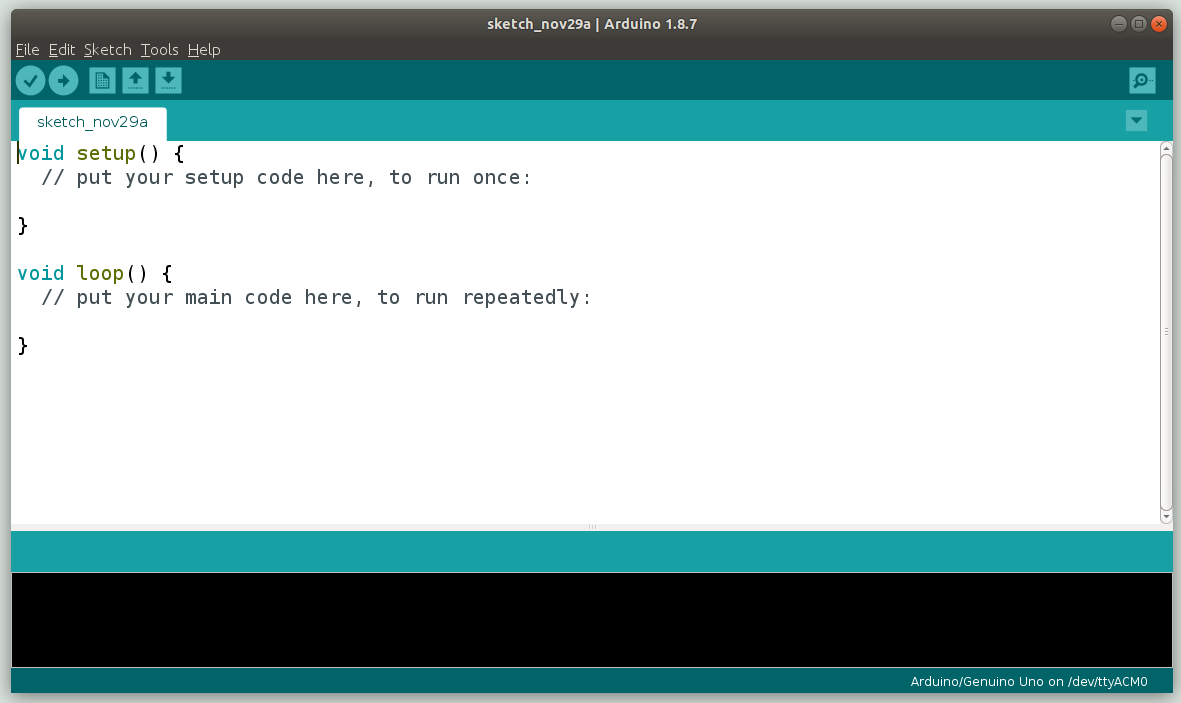
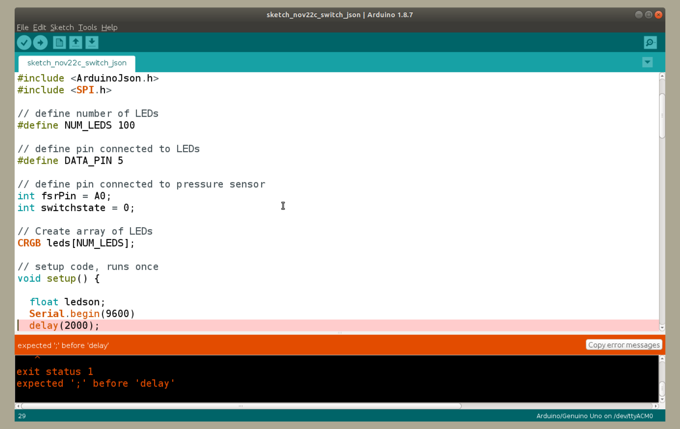
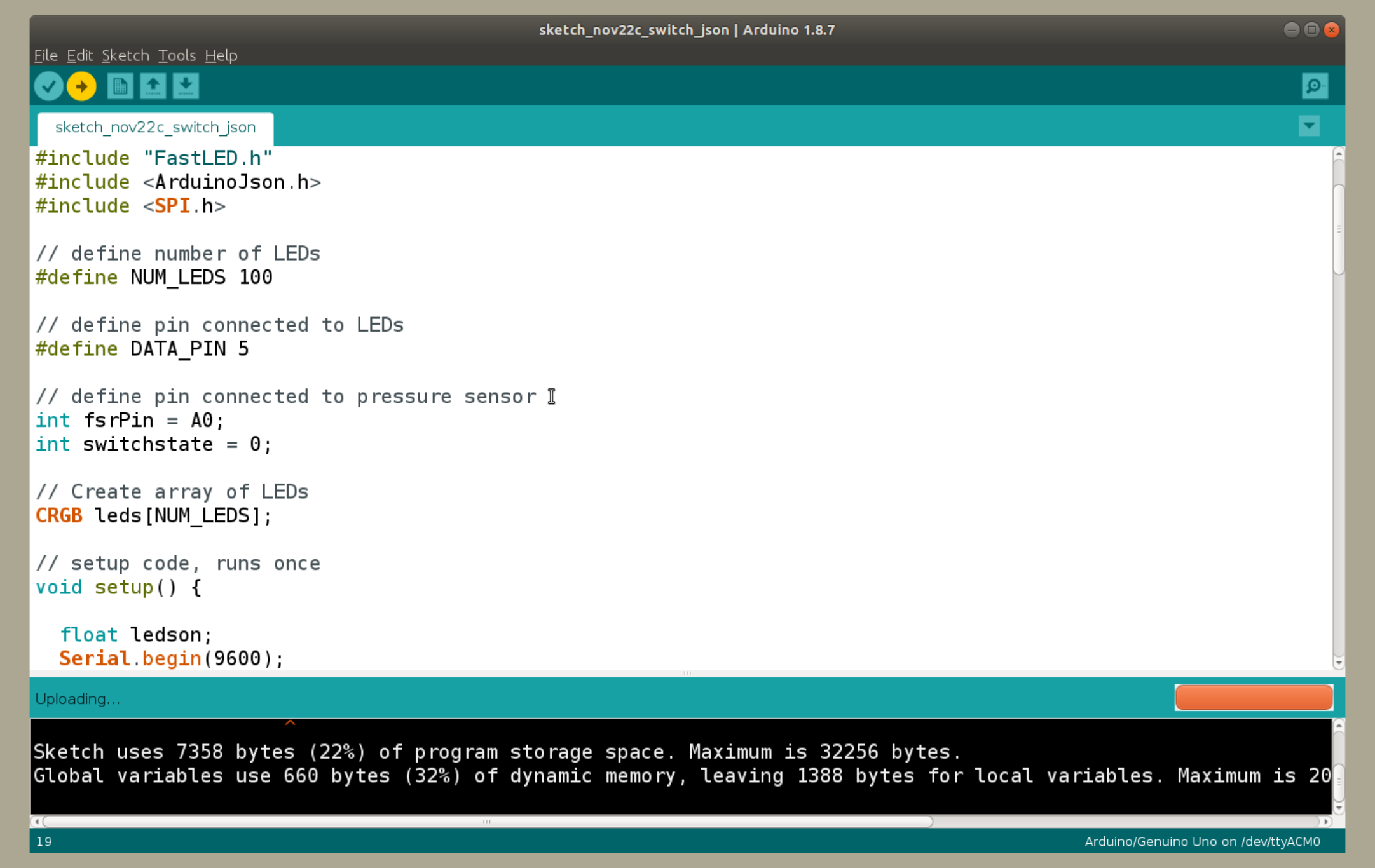
8. Once the code is in place, you can check it for errors by clicking the checkmark button in the top-left of the toolbar (see first image below). The bottom console will warn you of any errors to fix (see second image below).
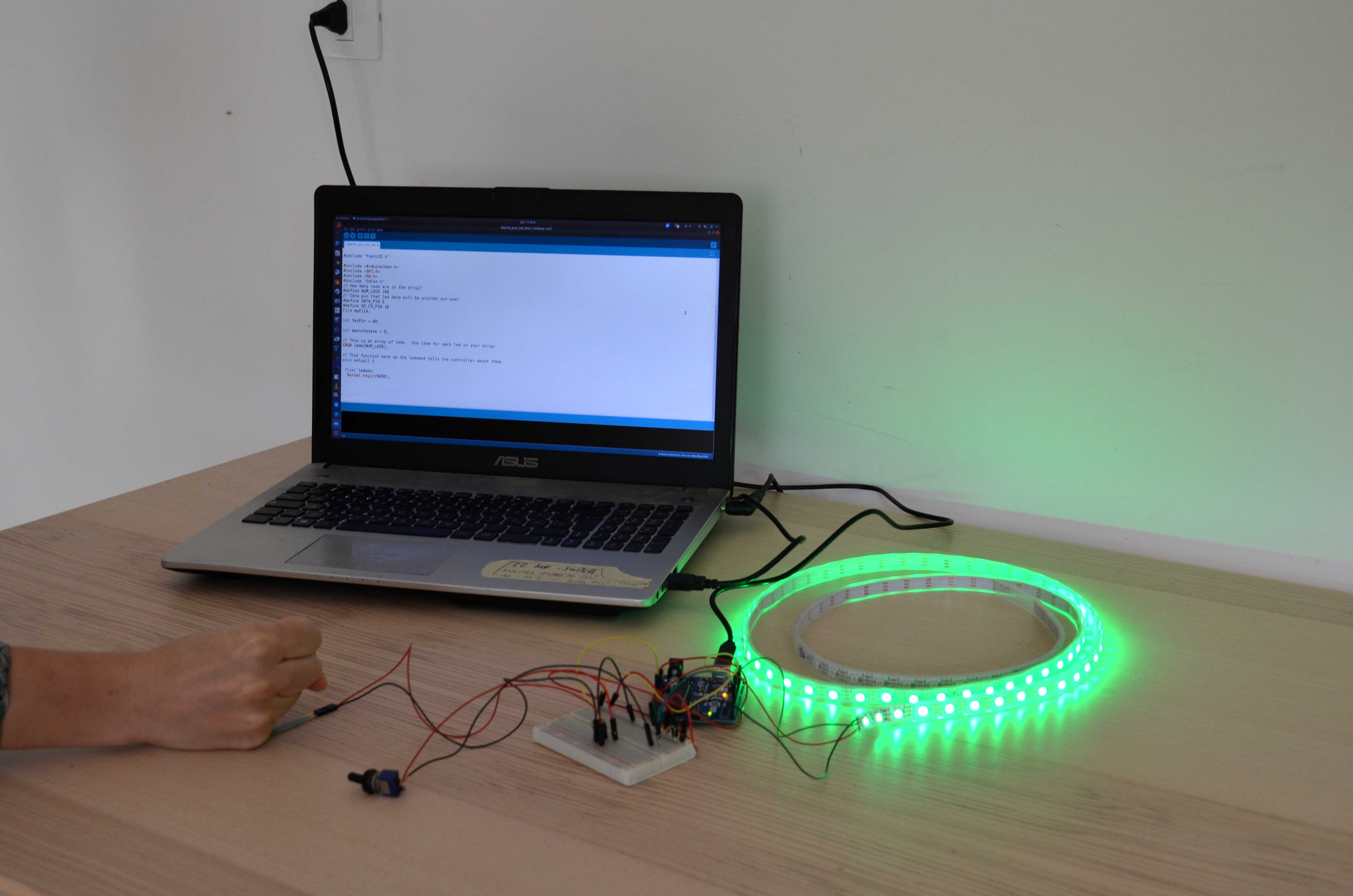
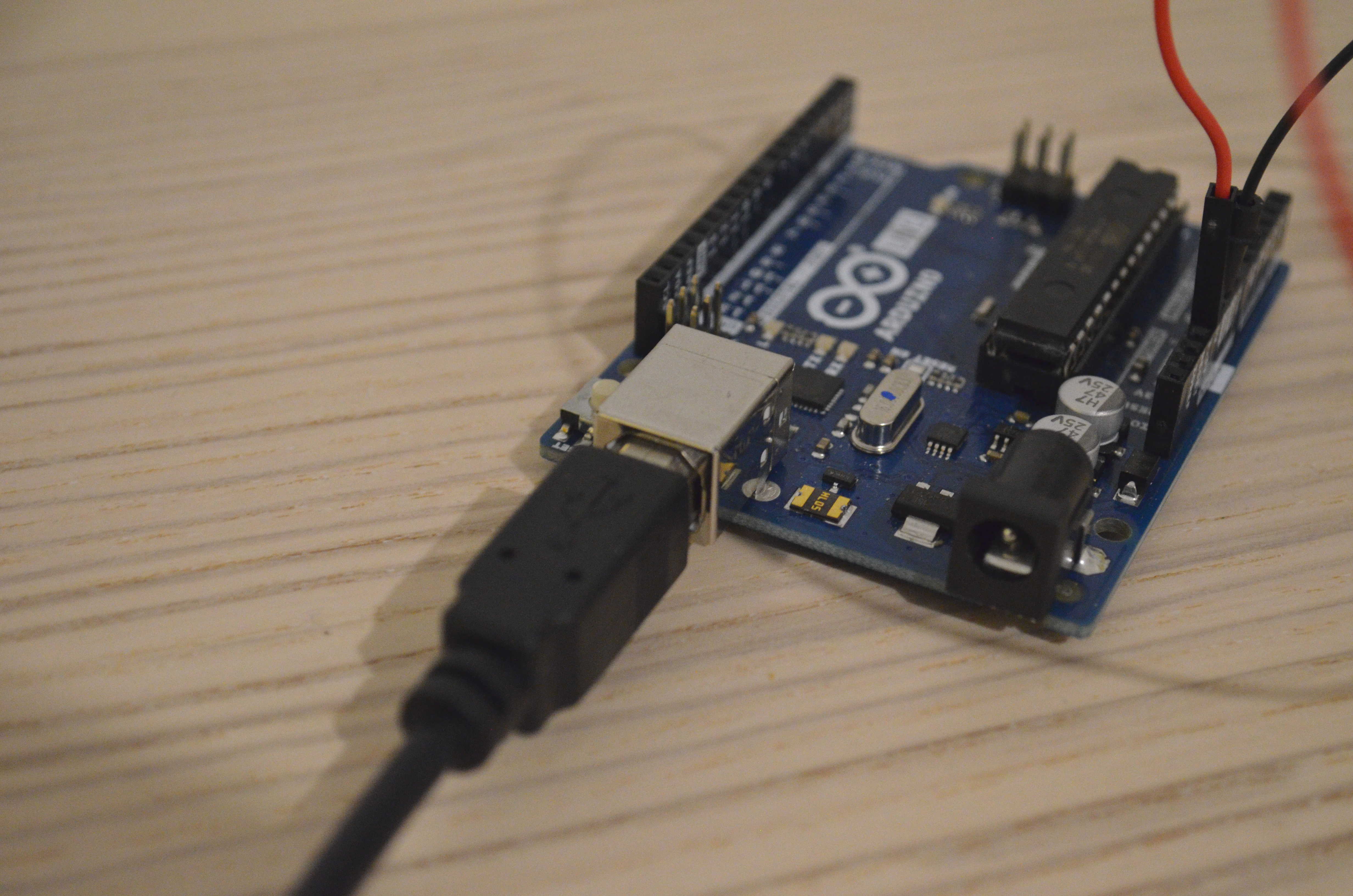
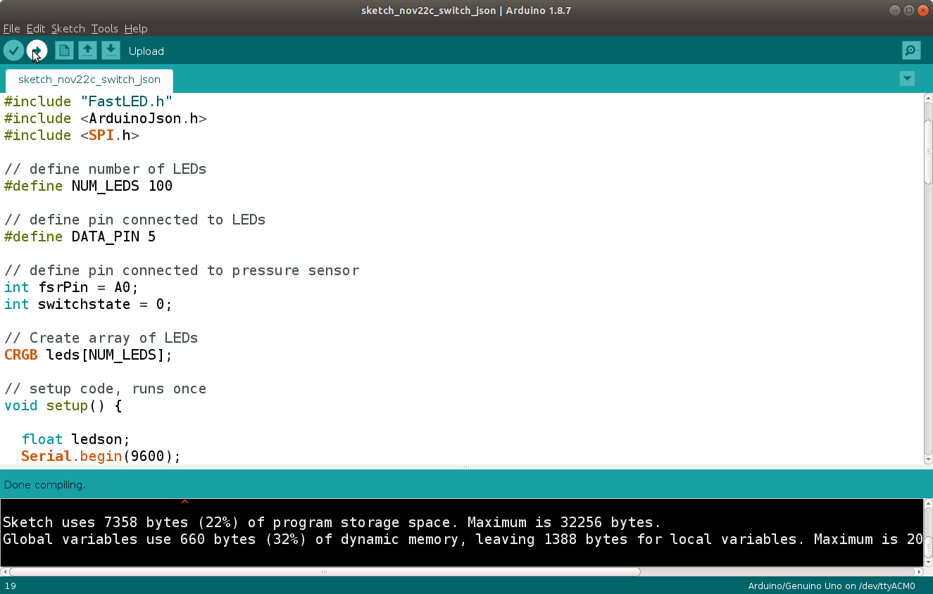
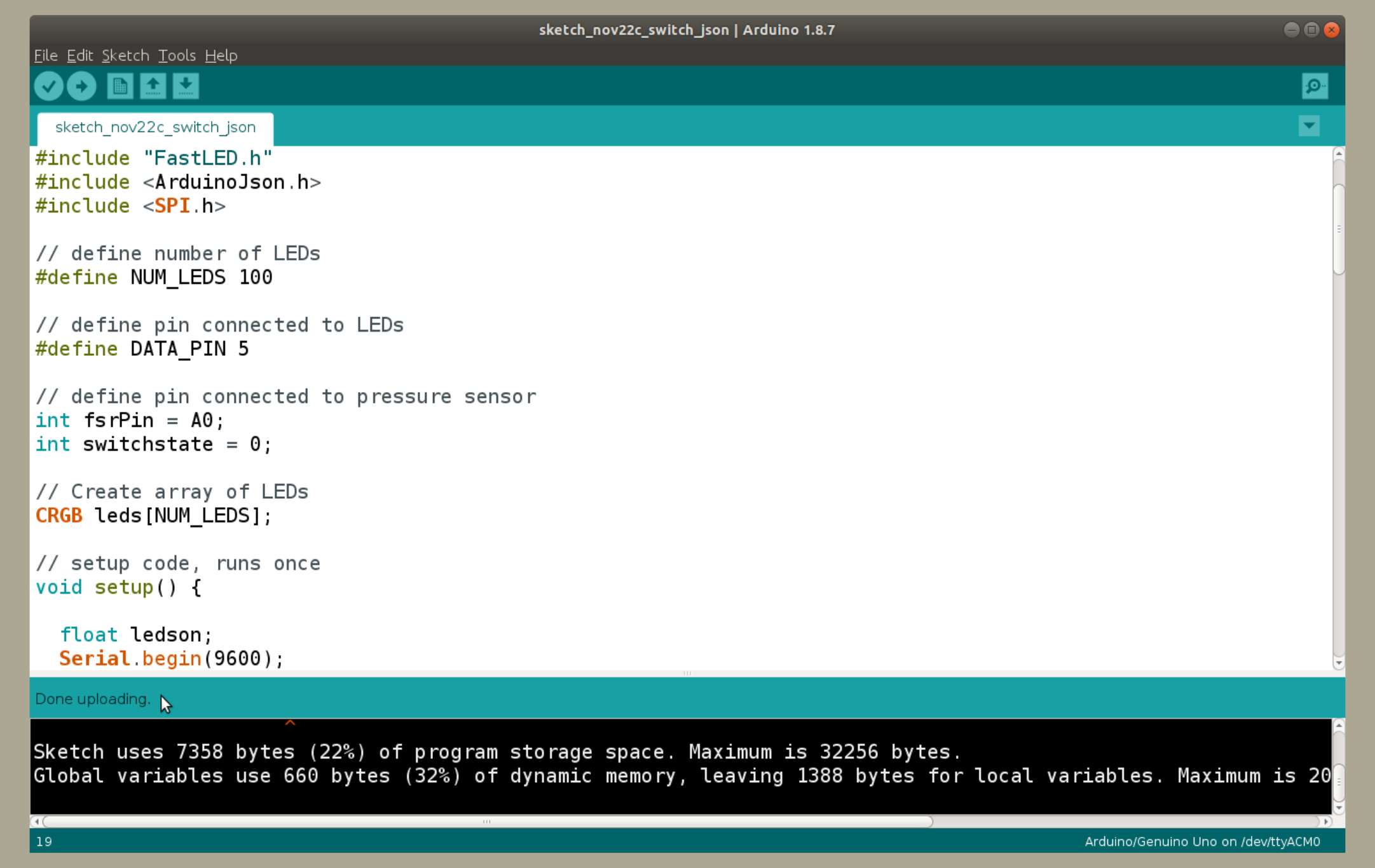
Once the code is verified, you can upload it into Arduino. First connect the board to the computer via USB (see third image below). On the Arduino IDE, click on the right-arrow button on the toolbar (see fourth image below). Wait for the upload to finish. Now you can test the actual functioning of the program and board by playing around with the switch and sensor. (See last image below).


9. To add more bars to the circuit, repeat steps 3-5 for each additional bar. You can refer to the following schematics as a guide to add the components. As the drawing shows, you need to add an external power supply to light multiple bars.
